
Subscribe to Our Youtube Channel
Related Manuals for Si-tex SP-70


Summary of Contents for Si-tex SP-70
- Page 1 SI-TEX MARINE ELECTRONICS INC INSTALLATION and OPERATION MANUAL SI-TEX SP-70 AND SP-80 AUTOPILOTS SI-TEX SP-80 AUTOPILOT SI-TEX SP-70 AUTOPILOT...
- Page 2 WARNING This Autopilot will automatically steer your vessel, however, it is only an aid to navigation. Its performance can be affected by many factors including equipment failure, environmental conditions and improper handling or use. This system does not reduce your responsibility for the control of the vessel when underway.
-
Page 3: Product Description
NAV MODE steers along a course line against overheating, protection against when the SP-70 or SP-80 is connected to computer failure or program error. an appropriate navigation device. SPECIFICATIONS In both PILOT and NAV Mode, pressing the Voltage: 10VDC - 40 VDC... - Page 4 SP-70/SP-80 System layout...
- Page 5 Si-Tex Processor: Part Number 30080003. Used on both SP-70 and SP-80 Autopilot packages. FOR SP-70 AUTOPILOT PACKAGES SP-70 Control Unit. Part Number 20080009. This part includes a curly cord wired to the Control Unit. SP-70 Control Unit Clip and Spacer. Part Number 65610010.
- Page 6 SP-70/SP-80 Fluxgate Compass. Part Number 20320003. This part includes 40 feet (12.2 m) of cable wired to the compass. In this group, one part the other part will be included: Rotary Rudder Feedback: Part Number 20330008. This part includes 50 feet (15.2 m) of cable wired to the Rudder Feedback.
- Page 7 • Accessory Kit: Contains a small screwdriver, extra terminal sockets and gland. • Control Unit Interconnection Cable (SP-70 systems only): 10 feet (3.05 m) of cable with a receptacle and cap on one end. Labelled as cable one. • Si-Tex SP-70 and SP-80 Autopilot Manual. Part Number 29010049.
- Page 8 INSTALLATION INSTRUCTIONS ARINE EVERSING Part Nos. 20810016, 20810031, 20810018 & 20810035 GENERAL: The reversing pump consists of a hydraulic pump and a motor. The pump is a piston type, driven by a reversing permanent magnet motor. The pump is designed in such a way that it will keep oil from returning through the pump when is not running or correcting.
-
Page 9: Tools And Materials Required To Install Pump
***** IMPORTANT ***** If the system you purchased includes a reversing motor pumpset, it is important that you apply and install this unit correctly. To ensure that you get the most from your purchase, read this installation and instruction manual carefully. By following the step-by-step procedure and using only basic tools and materials, you will find the installation easy to do. -
Page 10: Draining Your System
Planning The pump can be mounted in any orientation except with Port C facing downward. If Port Installation of the pump consists of: C is facing downward then air will not be able • Finding a mounting location for the to rise out of the pump and the pump will not have a supply of oil. - Page 11 You have a two-line system if you do not have the above components in your system. CAUTION CLEANLINESS must be maintained while making hydraulic connections. Contamination introduced into the steering system fluid can cause steering components to malfunction, possibly resulting in a loss of steering. Before beginning to connect the pump to the steering system, review the following installation hints: •...
-
Page 12: Hydraulic Connections For Two-Line Steering Systems
Hydraulic Connections For Two-Line Steering Systems A simple schematic of the pump installation is shown below. 2 Line Steering System Installation Delivery Lines: Ports A and B in the diagram above are the input/output ports of the pump and must be connected to the steering lines coming from the steering cylinder. -
Page 13: Hydraulic Connections For Three-Line Steering Systems
Hydraulic Connections For Three-Line Steering Systems A simple schematic of the pump installation is shown below. 3 Line Steering System Installation Delivery Lines: In the above diagram, Ports A and B are the input/output ports of the pump and must be connected to the steering lines between the steering cylinder and the Uniflow valve. - Page 14 Re-Fill And Bleed After you have installed your Pump, refill and bleed your manual steering system according to the manufacturer's directions. Any air, which is in the pump, will be expelled during the Set-up Routine. Technical Specifications Part Number: 20810016 20810031 20810018 20810035...
- Page 15 Connection between SP-70 Control Unit and Receptacle on Cable Number 1 SP-80 Control Unit and cable going to Si-Tex Processor...
-
Page 16: Installation Instructions
Splice and solder the joints. • The extension must be less than 10 feet Number 1 Cable from the SP-70 Control Unit (3 metres). Receptacle to the Processor is 10 feet long • Make the joints watertight by using heat- (3.05 metres). - Page 17 DRILL and a selection of DRILL BITS SMALL ADJUSTABLE WRENCH If you purchased a SP-70 or SP-80 with a Rotary Rudder Feedback you may need one stainless steel band clamp which is more than large enough to fit around your rudder post.
- Page 18 SP-70 Receptacle Installation The Receptacle is attached to the Number 1 cable. The diagram to the right shows the Receptacle mounted in a panel. Mount the receptacle near your normal steering position. The curly cord on the Control Unit lets you...
-
Page 19: Power Cable Installation
Power Cable Installation Fluxgate Compass Installation The Power Cable is labelled with a "5". Connect the Power Cable to a breaker capable of supplying twenty Amperes. CAUTION Keep the breaker turned off or do not connect the cable to the breaker. Fluxgate Compass Use the white wire for battery positive from the breaker. -
Page 20: Rotary Rudder Feedback Installation
Rotary Rudder Feedback Installation If you have purchased a SP-70 or SP-80 with an Outboard Feedback, please see the instructions titled, "Outboard Feedback". Select the following parts from your SP-70 or SP-80 package: BRASS BALL JOINT RUDDER FEEDBACK (INCLUDED WITH LINKAGE) - Page 21 Mounting the Rudder Feedback Rudder Feedback correctly installed to rudder post In the diagram above notice that: • the Rudder Feedback Arm is above the Use the Rudder Feedback as a template to cable entry gland; drill holes in the mounting surface. If you •...
- Page 22 Assemble Rudder Loosen the adjustment block that keeps the two pieces of the Rudder Feedback Linkage Feedback Arm from sliding. Measure the approximate diameter of your Snap the Rudder Feedback Linkage onto the rudder post in inches. two Brass Balls. Make sure to close the small release clamps on each Plastic Socket.
- Page 23 Flush Mounting the SP-80 Control Head Cut-out And Radius Dimensions for the SP-80 NOT TO SCALE...
-
Page 24: Outboard Feedback Installation
The Outboard Feedback is provided with 30 about the rudder or propeller position to the feet (9.1 metres) of cable. SP-70 or SP-80. The Outboard Feedback can be used with The Outboard Feedback can be attached to hydraulic cylinders from 1.25 to 2.25 inches. -
Page 25: Installation
Mounting Hardware Mount the Outboard Feedback so that it will not be damaged when the motor is tilted for trailering. Installation stainless steel band clamp. The clamp should be positioned as close as possible to the tube end where the cable exits. The Outboard Feedback may be mounted with the sliding rod facing either left or right. - Page 26 The Outboard Feedback should now be at half its full extension and attached to the outboard motor which is at the center position. Adjust the position of the Outboard Feedback so that as nearly as possible it is parallel with the hydraulic cylinder both horizontally and vertically.
- Page 27 Outboard Feedback Mounting to Front Mount Cylinder...
-
Page 28: Wiring The Processor
Wiring the Processor Place the Processor in front of you with the lettering right side up. Remove the four Phillips screws from each end. Remove the end pieces of the Processor enclosure. Looking into the open ends of the Processor you will see several green terminal strips. - Page 29 BLAC K O R BRO W N W HITE O R O R ANGE Right-hand side. Cable 1, Control Unit Note: There is an extra yellow wire in the cable that is not used. Pull all of the terminal strips from the right-hand end of the Processor. Note that there is an empty socket which does not have a terminal strip.
- Page 30 Right-hand side. Cable 2: Compass. Note: Yellow wire on terminal #2 may be substituted with a brown wire. Connections for Non SP-70/80 Fluxgate Compasses Be careful: The entire stripped end of the wire must be completely inside the terminal strip. Stripped sections of wire must not be able to touch each other.
- Page 31 Right-hand side. Cable 3, Rudder Feedback When you have completed the right-hand wiring, remove the terminal strips from the left Place the gland from the accessory kit in the hand end piece. hole. Fasten it with the supplied plastic nut and tighten securely.
- Page 32 Left hand side showing optional navigation input connection Use the diagram above to wire the navigation input. The terminal strip for this is in your Accessory Bag. See your LORAN, GPS, or plotter manual for information about wiring connections from that unit.
- Page 33 Left-hand side. Cable 5, power Connecting the ground FUSE REPLACEMENT In the picture above, the ground wire is the green wire. It is connected to the bolt beside The Si-Tex Processor is protected against terminal sockets power reversed power connection by a fuse. The connection.
- Page 34 Autopilot needs repair. The Installation of the SP-70 or SP-80 is complete. You are now ready to begin the "Set-up Routine". Mounting the Processor Once you have completed and checked the wiring, you are ready to mount the Processor.
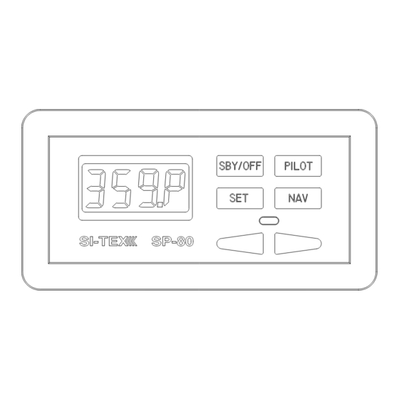
- Page 35 LOCATING THE “FLUSH KEY” SP-70 shown in the Pilot mode and steering a heading of 359 degrees On an SP-70 Control Head, the Flush Key is located immediately below the digital display and is flush with Control surface to prevent accidental button pushes.
- Page 36 SP-70 SET-UP ROUTINE (see page 50 for SP-80 set-up routine) The SP-70 must be OFF before you begin Press and hold the Flush Key (see the Set-up Routine. The first part of this page 44). Press and hold the Pilot Key routine can be done at the dock.
- Page 37 The display will show [HO S] The display will next show [HO P] (Hard Over (Hard Over to Starboard). to Port). Turn the steering wheel fully to the 2. Turn the steering wheel fully to the left. Press the Set Key. right.
- Page 38 CAUTION If you have installed a pump or retrofitted to In the next step, the SP-70 will move the an existing mechanical or hydraulic drive unit, steering system through its full range of you must now bleed and/or time your pump.
- Page 39 Press the Set Key. If the compass is a Fluxgate Compass the display will show [FLUH]. The Autopilot will next display [turn] (Turn). You must now adjust your compass. The Autopilot will next display a message about the compass type. Press the Set Key.
- Page 40 Check your hydraulic installation for any leaks or loose components. Slowly turn the boat in as small a circle as possible. Do not attempt to adjust the compass near a steel bridge, a submarine cable, or a steel It must take at least one minute to complete ship.
- Page 41 For Magnetic Compasses For Fluxgate Compasses If you have a magnetic compass Autopilot will display [nort] (north) the Autopilot will display [nort] (North). after successful calibration of the fluxgate compass (#10 in Set-up Routine). As accurately as possible, point your vessel to magnetic North and press the Point your vessel, or simply turn the Set Key.
- Page 42 SP-80 SET-UP ROUTINE SP-80 MUST BE OFF BEFORE YOU BEGIN THE Set-up Routine. The first part of this Press and hold the Flush Key (see Routine can be done at the dock. If you have page 32). Press and hold the Pilot Key a Fluxgate Compass, you will later repeat the until the display shows [FrST] and then first part away from the dock.
- Page 43 The display will show [HO S] The display will next show [HO P} (Hard Over to Starboard). (Hard Over to Port). 3. Turn the steering wheel fully to the left. Press the Set Key. Turn the steering wheel fully to the The display will show [WAIt] (Wait) for a few right.
- Page 44 IMPORTANT The steering gear will move from side to side. Move the steering wheel to the As the Autopilot tests the drive system the center position. display will show [d’tSt]. As the Autopilot checks the rudder the display will show [r’tSt]. The Output marks at the top of the display will show the direction of rudder movement.
- Page 45 Press the Set Key. If the compass is a Fluxgate Compass the display will show [FLUH]. The Autopilot will next display [tUrN] (Turn). You must now adjust your compass. The Autopilot will next display a message about the compass type. If you have a magnetic compass the display will show [nAG] (magnetic).
- Page 46 For Fluxgate Compasses Slowly turn the boat in as small a circle as possible. To fully adjust the Fluxgate Compass, it is necessary to take a short trip with your boat. It must take at least one minute to complete the turn.
- Page 47 For Magnetic Compasses For Fluxgate Compass If you have a magnetic compass If you have a fluxgate compass, the the Autopilot will display [nort] (North). Autopilot will display [nort] (North) after successful calibration of the fluxgate compass (#10 in Set-up Routine). Point your vessel, or simply turn the compass, until the compass is pointing North.
-
Page 48: Adding Capacity
Pump Bleeding Instructions have a helper, have them watch the oil Bleed your manual steering system level in the highest reservoir and refill it according manufacturer's when necessary. instructions. When you have completed the bleeding, leave the equipment for Your hydraulic cylinder rod is now fully the bleeding procedure attached to your extended in one direction. - Page 49 Bleeding cylinder, rod moving left Bleeding cylinder, rod moving right. If you are using a Reversing Pump, let The SP-70 or SP-80 will drive the pump the Autopilot drive the Reversing Pump until past the electronic rudder limit only when it nearly stops after the rod reaches the end of it’s travel.
- Page 50 the display shows [bLEd]. 11. Refill the highest reservoir. Refill your steering system from the highest reservoir. 12. Repeat steps 6 to 10 at least 10 times. Adjust the bleeding screws so that the 13. Close all bleeding screws or nipples. cylinder will be bled when the rod is Clean up any oil spills and wipe fittings extended in the original direction.
- Page 51 The SI-TEX Autopilot has a very wide range versions and last, vessel heading followed by of steering control settings. There are: a “P”. You are now piloting with the SP-70 or SP-80. To get manual command back, press • Four: Rudder Response settings.
- Page 52 Bring your boat onto a course. a few minutes, so you can measure its performance. The pilot may move back Turn ON the SP-70 or SP-80 Autopilot. To and forth across the desired course line. turn on the Autopilot, press the Pilot Key.
-
Page 53: Turns And Changing Course
While you are travelling slowly, it is a good you. If this new setting is still not suitable, time to practice using your SI-TEX Autopilot. repeat the instructions above. Continue this process until your vessel is steering well. - Page 54 Small Course Change Pressing the Red or Green Key in S TANDBY switches the Autopilot to Power Steer Mode. The display will have a degree symbol To make a one degree course change to the in the top right corner [xxx º]. You can now right, briefly press and release the Green use the Red and Green Keys to steer.
-
Page 55: Setting Fast Speed Rudder & Counter- Rudder Response
When your heading is correct, press the Pilot Key. The Press the Set Key. The display will show SP-70 or SP-80 will steer along the new [FASt] for five seconds. During this five course. second interval, press the Set Key two more... -
Page 56: Fast Speed Turns And Course Changes
Fast Speed Turns and Course To increase Rudder sensitivity: Press the Set Key. The display will show Changes [FASt] for five seconds. During this five Your vessel will respond more quickly to a second interval, press the Set Key again and Red or Green Key press than it did in the Autopilot will... - Page 57 Correct Vessel Response During a Course Change...
-
Page 58: Adjusting Your Digital Rudder Angle Indicator (Rai)
Angle Indicator (RAI) Many vessels always need the rudder positioned to the right or left a small amount. The SP-70 & SP-80 also provide an This slightly offset rudder position is needed electronic Rudder Angle Indicator. to correct for the turning effect of a single propeller. -
Page 59: Using Your Navigation Interface
The SP-70 or SP-80 will bring your boat onto the new course. It will steer towards the Waypoint using the information from the Nav device and the compass. -
Page 60: The Navigation Interface
The Navigation Interface Because of this, the SI-TEX Autopilot lets you change the way it interprets the direction of cross track error. In N , press the Your SI-TEX Autopilot will receive information Flush Key. The display will show either [---‘n] sent to it from a navigation device (such as a (normal) or [---r] (reversed). - Page 61 If you have further questions about the purchase of a navigation device, or if you experience difficulties using the N your SP-70 or SP-80 Autopilot, contact your SI-TEX dealer.
- Page 62 SP-70 and SP-80 Operation Commands COMMAND ACTION RESULT Steer by compass SP-70/80 is off or in S Boat will settle on course. TANDBY Display will show [xxxP]. Point bow and press Pilot x x x P Key. Immediately upon pressing the...
- Page 63 Press Green Key to increase or Red Key to decrease brightness. Change from compass In P , press The SP-70 or SP-80 will constantly OWER TEER display to permanent rudder the Set Key. display the rudder angle while in angle display.
-
Page 64: Adjustment Commands
Adjustment Commands COMMAND ACTION RESULT Autopilot will steer with a “harder” Rudder sensitivity: increase or N ILOT turn to correct course deviations, Press Set Key twice. causing a shorter correction, but more overshoot of the intended Press Green Key. course. Changes will only affect the current speed (fast or slow) sensitivity setting. - Page 65 HECK Cancel the alarm using the Pilot Key. The message will reappear whenever the SP-70 or SP-80 is in Pilot Mode. The digital and analog RAI will not work. The battery voltage is more than 40 volts. If this problem is not fixed, the Processor could be damaged.
- Page 66 : The Processor and the Processor space for heat sources. HECK Should the temperature rise still higher, the SP-70 or SP-80 will turn off the steering outputs. When the temperature falls, the steering outputs will turn back on. We recommend that you have the Autopilot serviced by a SI-TEX dealer before it is used again.
- Page 67 Port Rudder indicator (digit) (digit)* PRON EPROM Error. This indicates a failure in the Processor. Take the Autopilot to a SI-TEX service center. Ram Error. This indicates a failure in the Processor. Take the Autopilot to a SI-TEX service center RED0 Occurs during Set up Routine.
-
Page 68: Problems Without An Error Code
The random occurrence of this problem is possible but unlikely. If this problem occurs twice, your Autopilot may need servicing. Contact your SI-TEX dealer. The Control Head display The SP-70 or SP-80 Control Head may be disconnected. goes blank, Autopilot... - Page 69 APPENDIX A Connections to 4 and 5 Wire Motors...
- Page 70 APPENDIX A Connections to 4 and 5 Wire Motors (using a clutch or lockup valve) Rated for 3 amps continously/5 amps intermittently...
- Page 71 APPENDIX B Connections to Solenoid Valves...
-
Page 72: Connecting A Second Location Or Second Station Options
SP-70 Control head at several locations. If you chose this method, it is important to note that only one SP-70 Control Head can be connected at any given time. You are in fact only moving your Control Head from one location to another. -
Page 73: Second Station Kit
To connect the cable, first loosen off the right-hand cap on the SI-TEX Processor Box and remove the “knock-out” at the top of the cap by using a 9/32 inch (7mm) drill. Once the “knock-out” has been removed, install the cable gland and the cable. Next connect the individual wires on the second location cable to the middle terminal strip, paralleling the existing main receptacle wiring (Cable 1). -
Page 74: Operation
The Second Station is identical in operation to the Main Station as described in “Piloting with the SP-70 or SP-80 Autopilot”. Only one of the controls can operate the autopilot at any given time. The unit that is non-active will have a continuously flashing LCD display and the active control will have a steady display. -
Page 75: Connecting A Rudder Angle Indicator
APPENDIX D Connecting a Rudder Angle Indicator Right-hand side showing optional RAI connection. The cable gland for a rudder angle indicator is in your Accessory Bag. We do not supply a cable for this installation but recommend a #22 gauge, two conductor cable that is round in order to make a water-tight seal. -
Page 76: Connecting The Nmea 0183 Heading Output
J5 and the other wire (return) connects to pin 2 of terminal strip J5. Terminal strip J5 is located in the lower right side of the SP-70 Processor circuit board (see above). The two pin connector required for connecting the heading output is included in your accessory kit. - Page 77 SI-TEX MARINE ELECTRONICS INC INSTALLATION and OPERATION MANUAL SI-TEX SP-70 AND SP-80 AUTOPILOTS Addendum 1 Wiring the Control Unit & Compass (New Cable Colour Codes) SP-80 AUTOPILOT SP-70 AUTOPILOT...
- Page 78 Compass cable. This cable has a different colour code than the original cable type, although it is otherwise identical. As well, there is now an alternate SP-70 Control Unit Receptacle cable, with a different colour code than the original cable.
- Page 79 Caution: there are some differences in hand end of the Processor. the colour codes of the cable types that can be used for Cable 1 (the SP-70 Note that there is an empty socket that Receptacle, or the SP-80 Control Unit), does not have a terminal strip.
- Page 80 SI-TEX SP-70 & SP-80 Autopilot Systems Original Alternate Cable Cable Colours Colours GREEN GREEN PINK BLACK GREY BLUE YELLOW WHITE WHITE YELLOW BROWN SHIELD SHIELD Right Side, Cable 2 (Compass) to J6 Be Careful The entire stripped end – but no portion of the insulation – of all wires into the terminal strip plugs must be completely inside the plugs.
Need help?
Do you have a question about the SP-70 and is the answer not in the manual?
Questions and answers