Si-tex SP-110 Installation And Service
Hide thumbs
Also See for SP-110:
- Manual (8 pages) ,
- Installation and service (24 pages) ,
- Operation (6 pages)
Table of Contents
Advertisement
Advertisement
Table of Contents

Subscribe to Our Youtube Channel
Related Manuals for Si-tex SP-110


Summary of Contents for Si-tex SP-110
-
Page 1: Si - Tex . Com
SP-110 Autopilot INSTALLATION AND SERVICE www.si-tex.com... - Page 2 BLANK PAGE SI-TEX SP-110 – SS30 10/25/2011...
-
Page 3: Table Of Contents
LARM GPS A ......................19 LARM ....................19 EFINITION OF ERMS ..................19 VERVIEW OF PERATION ....................21 ROUBLE HOOTING ....................22 CHEMATIC IAGRAM ......................23 ARRANTY SI-TEX .. 24 DDITIONAL NFORMATION EFER TO WEBSITE SI-TEX SP-110 – SS30 10/25/2011... -
Page 4: Warning
INTERFERENCE CAN ENDANGER YOUR OWN OR OTHER VESSELS. IF A GPS IS CONNECTED TO THE SYSTEM AND USED AS THE HEADING SOURCE AT A SPEED OF ONE KNOT OR LESS THE SYSTEM WILL DISENGAGE FROM AUTO. SI-TEX SP-110 – SS30 10/25/2011... -
Page 5: Sp-110 Autopilot System
Rudder Feedback Unit (SP-110R only). In addition the SP-110 has to be connected to a drive unit which controls the rudder actuator system in order to complete the full autopilot system. The actuator system provides the physical movement to the rudder responding to the direction of control signals provided by the SP-110. -
Page 6: Installation Of System Components
The compass must be mounted a minimum distance of 1 metre form any boat compass, radios, speakers or other products with magnetic properties to avoid interference. The SP-110 must have a direct connection to power supply via a 15 amp circuit breaker or a 15 amp fused circuit and an isolating switch. -
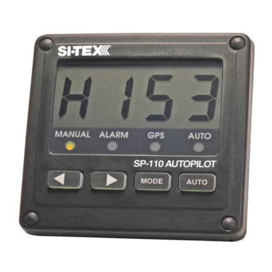
Page 7: Display Unit
Display Unit Position: The SP-110 Head unit should be mounted in a position accessible to the steering position and protected from direct rain or salt water Select a dry position For in dash mounting cut a 70mm (2.5”) hole (an optional mounting bracket is available and may be used for display mounting –... -
Page 8: Compass
Mount the compass horizontally with the arrow (bow) pointing in the same direction as the boat’s bow. Use non magnetic screws (304 grade stainless steel) Run cable to SP-110 display position (keep away from other cables) Connect compass cable to SP-110 compass socket Compass Mounting SI-TEX SP-110 –... -
Page 9: Rudder Feedback Unit
Route cable to SP-110 display position Connect rudder feedback cable to SP-110 rudder socket When installation is complete, slowly move the steering by hand to ensure: a) The direction indicated on the top of the RFU is correct b) No undue mechanical strain is placed on the feedback or linkage NOTE: The rudder feedback unit is water resistant. -
Page 10: Rudder Feedback Installation Diagram
Note: Pin locations are relative to pin 1 which always has a dot adjacent. NOTE: The rudder feedback is factory aligned. The arm should not be removed or loosened the shaft as this will affect the “O” ring seal. Octopus Mechanical Drive RFU Connections SI-TEX SP-110 – SS30 10/25/2011... -
Page 11: Gps Wiring Connections
Note: For information on connecting different brands of GPS units, refer to the relevant GPS manual Hydraulic Reversing Motor Connection Route suitable two core cable (10 amp min) from motor to SP-110 display Connect motor cable to the yellow and yellow/black motor wires at SP-110 Notes:... -
Page 12: Motor Connections
Motor Connections SI-TEX SP-110 – SS30 10/25/2011... -
Page 13: Solenoid Valve Use
Solenoid Valve use, Wire the solenoid valves to Yellow and the 12 volt power feed and Yellow with Black stripe and 12 volt power feed on second terminal block. Ensure 12 volt is via a suitable fuse, less than 5 amps. SI-TEX SP-110 – SS30 10/25/2011... -
Page 14: Initial Operational Settings
Initial Operational Settings The initial set up of the SP-110 is done once the system installation is complete and power has been connected to the SP-110 display control. The set up can be done automatically or manually Automatic installation set up determines the output polarity for motor direction and rudder limit setting. -
Page 15: Sensitivity
Press MODE again until display shows SL - - (starboard limit) Turn boat helm until rudder reaches required angle – example 28º stbd Press ◄ and ► together to save this setting Press AUTO to return to MANUAL SI-TEX SP-110 – SS30 10/25/2011... -
Page 16: Compass Heading
Re-tighten the screws Technical Adjustments These procedures are used to adjust internal parameters of the SP-110. Routines 1, 2 and 4 are not used in the SP-110R. Each routine can be set or reset and can be displayed individually To enter the procedures: ... -
Page 17: Sp-110 Default Settings
3. Dead Band 4. Pulse Frequency 5. Minimum Speed 1 (knot) rf – 0 6. No RFU 7. Not used 8. Auto Trim Timer A BOD Correction Factor 15 B Pulse type C Wind damping SI-TEX SP-110 – SS30 10/25/2011... -
Page 18: Setting Up Your Gps Unit
“arrival zone” of more than 0.05 NM (Nautical Miles) is set so that the GPS can detect when the vessel has reached a waypoint; then the SP-110 will be able to steer from each waypoint to the next without intervention. -
Page 19: Gps Alarm
GPS Alarm In waypoint steering mode an audible alarm of 1 “beep” per second will sound when no GPS data is received by the SP-110. ALARM and GPS lights will also flash on and off. Definition of Terms SP-110 Display: The operational control unit with LCD display and push buttons. - Page 20 Press arrow button to operate steering in that direction Check that rudder moves in correct direction Check Rudder direction follows change request Check Course change provides sufficient Rudder movement Check magnetic heading display on SP-110 10. Return steering to centre SI-TEX SP-110 – SS30 10/25/2011...
-
Page 21: Trouble Shooting
Confirm SP-110 display is showing heading information. Check voltage is present at the SP-110 motor connections (Yellow and yellow with black stripe) when AUTO is selected and a course change applied. Confirm that the supply voltage is 12 volts DC (Red and Black). -
Page 22: Schematic Diagram
Schematic Diagram SI-TEX SP-110 – SS30 10/25/2011... - Page 23 SI-TEX SP-110 – SS30 10/25/2011...
-
Page 24: Warranty
SI-TEX shall not be liable for damage or loss incurred resulting from the use and operation of this product. SI-TEX reserves the right to make changes or improvements to later models without incurring the obligation to install similar changes to equipment already supplied.
Need help?
Do you have a question about the SP-110 and is the answer not in the manual?
Questions and answers