
Subscribe to Our Youtube Channel
Related Manuals for Si-tex SP38


Summary of Contents for Si-tex SP38
- Page 1 Sitex SP38 Autopilot Advanced Autopilot Systems Installation and Operation Manual PN 29010101...
-
Page 2: Welcome
Welcome Congratulations on your purchase of a Sitex Marine SP38 Advanced Autopilot System. Developed using Sitex’s many years of experience in autopilot design, the SP38 Autopilot provides superior performance and advanced features, meeting or exceeding any other products in their class. -
Page 3: About This Manual
About this Manual This manual provides essential information for the safe and reliable operation of the Sitex SP38 Advanced Autopilot System. You are urged to read this manual in its entirety before you use your autopilot for the first time, and to keep it handy until you become thoroughly familiar with the operation of your autopilot. -
Page 4: Manual Format
Sitex SP38 Installation and Operation Table of Contents, List of Figures and Tables Manual Format Date Description 16 August 2018 First Release This manual has been formatted to be printed on both sides of the pages, and on standard North American Letter-size paper (8.5” x 11”). -
Page 5: Document History
Sitex SP38 Installation and Operation Table of Contents, List of Figures and Tables Document H istory Revision: Date: By: Description: 1R0 November 2 018 First R elease ... -
Page 6: Table Of Contents
Sitex SP38 Installation and Operation Table of Contents, List of Figures and Tables Table of Contents Welcome ......................... 2 About this Manual ............................ 3 Typefaces, Common Phrases and Terms ....................3 Manual Format ............................4 Document History ............................ 5 Table of Contents ......................6 List of Figures ............................ - Page 7 Sitex SP38 Installation and Operation Table of Contents, List of Figures and Tables Installation ..........................43 Basic Requirements ..............................43 Steering System ..............................43 Power Supply ................................43 Special Tools ................................43 Fasteners ................................. 43 Control Head ................................44 Electrical Connection ............................... 44 Signal Processor Unit ..............................
- Page 8 Sitex SP38 Installation and Operation Table of Contents, List of Figures and Tables Getting Started ........................72 Autopilot Operations ..............................73 Power On/Of ................................73 Using the Control Head – LCD Screen and Buttons ....................75 Operating Modes and Menus ..........................76 Advanced Operations .............................
- Page 9 Sitex SP38 Installation and Operation Table of Contents, List of Figures and Tables Basic Operations ......................... 121 Control Head LCD Screen and Buttons ......................... 122 Operating the System ............................124 Mode Menus ................................124 Rudder Angle Indicator ............................126 Power On ................................127 Power Off ................................
- Page 10 Sitex SP38 Installation and Operation Table of Contents, List of Figures and Tables Advanced Operations ......................151 WORK Mode ................................ 152 Work Menu ................................155 Rudder Bias ................................. 155 Autotrim ................................155 Work Trip Pt. (Work Trip Point) ..........................155 Rudder Scale (Rudder Scale Factor) ........................
- Page 11 Sitex SP38 Installation and Operation Table of Contents, List of Figures and Tables Compass Safe Distances ............................180 CE Compliance ..............................181 Warranty Information ............................. 182 Cutomer Service ..............................185 Index ..................................186 User Notes and Settings ............................189 - 11 -...
-
Page 12: List Of Figures
Figure 3 – SP38 System Block Diagram ......................28 Figure 4 – Control Head ..........................29 Figure 5 – The SP38 SPU with Wiring and Diagnostic Covers Removed ............30 Figure 6 – G2 GPS Compass ......................... 31 Figure 7 – Navigator G2 Display Head ......................32 Figure 8 –... - Page 13 Sitex SP38 Installation and Operation Table of Contents, Lists of Figures and Tables Figure 50 – A Typical Menu ..........................81 Figure 51 – Set Vessel Type ......................... 104 Figure 52 – Set Compass Type ........................107 Figure 52a – Using the Control Head ......................122 Figure 53 –...
-
Page 14: List Of Tables
Table 6 – Nav Mode Correction ........................142 Table 7 – Fuse Replacement Guide ......................167 Table 8 – NMEA 0183 Sentences Accepted by the SP38 ................171 Table 9 - NMEA Sentence Priority ........................ 172 Table 10 – Warning Messages ........................174 Table 11 –... - Page 15 Sitex SP38 Installation and Operation Table of Contents, Lists of Figures and Tables - 15 - Document PN 29010101 V1r0...
- Page 16 Sitex SP38 Installation and Operation Introduction - 16 - Document PN 29010101 V1r0...
- Page 17 Sitex SP38 Installation and Operation - 17 - Document PN 29010101 V1r0...
-
Page 18: How Autopilots Work
There are a number of parameters used in the steering algorithms, collectively referred to as “Steering Parameters.” The SP38 Autopilot system has been tested on a wide variety of boats, of different types and sizes. The default settings for the Steering Parameters are average values derived from that testing, and provide a good starting place for most boats. -
Page 19: Basic Autopilot System
Sitex SP38 Installation and Operation How Autopilots Work Basic Autopilot System Figure is a block diagram of the major components of an autopilot system. NAVIGATION DEVICES CONTROL HEAD [OPTIONAL] DISPLAYS STATUS AND HEADING SUPPLY NAVIGATION INFORMATION FROM THE SPU, AND... -
Page 20: Autopilot Operation: Maintaining A Heading And Current Effects
How many degrees the rudder moves depends on the type of vessel, and its dynamics (which you have specified and tested when you set up the autopilot). Note: On a SP38 Autopilot with an RFU, the SPU verifies that the rudder has moved, by reading its position from the RFU. - Page 21 Sitex SP38 Installation and Operation How Autopilots Work • On the other hand, if the boat is coming back too quickly, the rudder will be moved quickly back to dead-ahead – or maybe even a bit to Port for a few seconds.
-
Page 22: Figure 2 - Heading Change In Auto Mode
Sitex SP38 Installation and Operation How Autopilots Work Changing Heading Heading changes are very simple with a Sitex autopilot as well. Imagine for example, that the autopilot is steering your boat Southwest, and you now wish to change direction to Southeast... - Page 23 Sitex SP38 Installation and Operation How Autopilots Work Wind and Current Effects If your vessel encounters a crosswind, and/or a tidal current at any given angle to the desired Heading, it will be pushed away, in the direction of the wind or current. At this point, the autopilot will constantly be making Heading corrections with the rudder, as it tries to maintain your desired Heading.
- Page 24 Sitex SP38 Installation and Operation How Autopilots Work Cross and/or currents are compensated for automatically each time the Navigation System updates the Cross-Track Error. This is why NAV mode is the answer to the “track slip” problem that can occur in AUTO mode, when a cross/current exists.
-
Page 25: Power Steer
How Autopilots Work Following a Track: AUTO/ALC Mode Some Sitex autopilots (including the SP38), provide another way to keep your boat on a specific Track: Automatic Leeway Correction. This feature can be turned on in AUTO mode. ALC is similar to NAV mode, in that it uses NMEA0183 or NMEA2000 Latitude and Longitude data to sense if the boat is following the desired Track. -
Page 26: System Overview
Sitex SP38 Installation and Operation How Autopilots Work System Overview - 26 - Document PN 29010101 V1r0... - Page 27 Sitex SP38 Installation and Operation System Overview System Overview This chapter provides a brief description of the major elements of the SP38 Advanced Autopilot System, its functions, and their relationships to each other. Figure 3 shows a block diagram of a typical example of the SP38 system, showing the interconnections between the elements of the system: •...
-
Page 28: Figure 3 - Sp38 System Block Diagram
Sitex SP38 Installation and Operation System Overview Block Diagram of the SP38 System NMEA 2000(N2K) Connection - Trunk (Backbone) cable NMEA 2000(N2K) Connection - 6m drop cable, Male & Female (PN31110052) NMEA 2000(N2K) Connection - 6m cable, Pigtail & Male (PN31110073) -
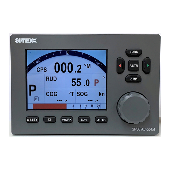
Page 29: Control Head
Figure 4 – SP38 Control Head The Control Head, when shipped as part of a complete SP38 system, is a “core” module, with accessories for mounting option: bracket for bracket mounting. All required hardware is included, except for two fasteners needed to fasten the bracket to a mounting surface. -
Page 30: Signal Processor Unit
Rudder Feedback, Sitex RAI, NMEA 0183 Interfaces and Rudder Drives and Interfaces). The SP38 SPU connects to a NMEA 2000 network or standalone with a supplied T-connector to the SP38 Head, via a supplied 1m NMEA 2000 (Pigtail & Male End) cable at the Network Port of the SPU. -
Page 31: Compasses
System Overview Compasses The Compass is a critical component in the proper operation of the SP38 Autopilot System. The autopilot system’s ability to steer the vessel to a given Heading desired by the Operator can only be as accurate as the Compass. -
Page 32: Figure 7 - Navigator G2 Display Head
The GNSS NMEA0183 model is connected to the SP38 Autopilot at one of the SPU’s two NMEA Input ports. The standard cable lengths are 15 metres (50’) or 30 metres (100’);... -
Page 33: Fluxgate Compass
8) connects the Display Head(s) to a GNSS G2/G2B, and has a convenient set of terminal strips for connecting power, the signals to and from it, as well as the signals to the SP38’s SPU. It also has a connector for the cable to a PC’s COM port. Figure 8 –... -
Page 34: Magnetic Compass Sensor
Sitex SP38 Installation and Operation System Overview Magnetic Compass Sensor PN 20320002 The Sitex Magnetic Compass Sensor (Figure 10) detects the position of the compass card of an externally gimballed magnetic compass. The sealed unit can be attached to the bottom of any of Sitex’s Magnetic Compasses, or the bottom or top of many other brands of externally... -
Page 35: Other Compasses
See your Sitex Dealer or consult the factory for information on interfacing these compasses with the SP38 system. Rudder Followers... -
Page 36: Jog Levers
Sitex SP38 Installation and Operation System Overview Figure 13 – Heavy Duty Rotary Rudder Follower Other Controls, Indicators and Sensors Jog Levers PN 20310002 (1 set of switches) PN 20310003 (2 sets of switches) Sitex’s Non-Follow-Up (NFU) Jog Lever is a permanently mounted, watertight, electrical switch specifically designed for marine use. -
Page 37: Figure 15 - External Rudder Angle Indicator - 3" Model
Sitex SP38 Installation and Operation System Overview Figure 15 – External Rudder Angle Indicator - 3" Model - 37 - Document PN 29010101 V1r0... -
Page 38: Rudder Drives And Interfaces
It has standard voltage outputs, current loop outputs and optically-isolated analog outputs. The CT7 also contains circuitry for interfacing an Electric Wheel to the SP38 system, and a Rudder Simulator which is used when the CT7 is interfaced to Azimuth Drives. -
Page 39: Other Drive Boxes
Sitex SP38 Installation and Operation System Overview Other Drive Boxes The SP38 system is capable of directly operating steering systems utilizing reversing DC motors or single speed solenoids. Sitex also manufactures a complete line of Drive Boxes that will interface the steering outputs from the SP38 system to almost any type of steering system. -
Page 40: Pumps And Drives
- Continuous Running Electric Pump Other Equipment Besides the optional equipment described above, there is a wide choice of other equipment available for use with the SP38 Advanced Autopilot system. Contact your Sitex Dealer for information and details. - 40 -... - Page 41 Sitex SP38 Installation and Operation - 41 - Document PN 29010101 V1r0...
- Page 42 Sitex SP38 Installation and Operation Installation - 42 - Document PN 29010101 V1r0...
-
Page 43: Installation
Sitex SP38 Installation and Operation Installation This chapter describes all the steps you must follow to physically install a P-Series Autopilot System into your vessel. Each of the standard components of the system are described, both physical mounting and electrical wiring, and then some final checks are provided. Commonly-used accessories are also described. -
Page 44: Control Head
Control Head The SP38 Control Head is typically mounted in the vessel’s wheelhouse. It can also be mounted in more exposed locations, such as on a flying bridge, since it is fully splash-proof (however be advised that the SP38 Control Head is not submersible). -
Page 45: Compasses
Sitex SP38 Installation and Operation Compasses Sitex SP38 autopilot systems are typically supplied as a complete System Kit, with one of several types of available compasses; the compass type chosen typically depends on the type and intended use of the boat. -
Page 46: Electrical Connection
Sitex SP38 Installation and Operation Electrical Connections Route the Compass Transducer cable from the compass to the location where the SPU will be. Avoid running the cable parallel to antenna cables, AC power, or DC wires/cables carrying heavy current. Excess cable should be coiled up. The cable may be shortened if desired to avoid excess coils. If the cable is too short, additional cable may be ordered from your Sitex Dealer. -
Page 47: Rudder Follower
Rudder Follower in a location where the possibility of damage from any equipment stowed in the area is minimized. Note: If you are connecting the SP38 to a mechanical Cable Drive (for vessels that use cable steering instead of hydraulic steering), the rudder follower is built into the Cable Drive. See the Cable Drive Installation Manual for details. -
Page 48: Rotary Rudder Follower
Sitex SP38 Installation and Operation Rotary Rudder Follower Mounting Install the Rudder Post Arm on the rudder post using a stainless steel band clamp (not supplied). Bolt the ball joint to the hole in the Rudder Post Arm corresponding to the diameter of the Rudder Post in inches, making sure the ball is facing upwards. -
Page 49: Heavy Duty Rotary Rudder Follower
See the Rudder Follower section for further details on connecting the cable to the SPU. Heavy Duty Rotary Rudder Follower The Sitex Heavy Duty Rotary Rudder Follower is also compatible with the SP38 Advanced Autopilot System. If you have purchased one of these devices, follow the installation instructions supplied with the unit. -
Page 50: Signal Processor Unit
Sitex SP38 Installation and Operation Signal Processor Unit Mounting The SPU should be mounted in a clean and dry area, away from heat, moisture, and liquids of any kind. The SPU should be centrally located, and mounted far enough away from your vessel’s compasses so as to minimize any possible electrical interference;... -
Page 51: Power Supply
Sitex SP38 Installation and Operation Note that the plug screws must be turned counter-clockwise several turns (using a small slotted screwdriver), to open up the plug’s wire clamp, before a wire is inserted into that clamp; the screw must then be turned clockwise until the wire is tightly held in the clamp. -
Page 52: Wiring The System
Sitex SP38 Installation and Operation The Sitex SP38 will operate on any voltage of 12 VDC and 30 VDC. This allows operation with vessel battery systems of nominal voltages from 12 to 24 VDC. Caution! Do not power up the SPU until you have completed the installation, and performed the steps outlined in “Post-Installation Checks.”... -
Page 53: Figure 24 - Typical Battery Connection To Head
Sitex SP38 Installation and Operation **ORANGE & BROWN WIRES ARE FOR FUTURE Figure 24 – Typical Battery Connection to Head - 53 - Document PN 29010101 V1r0... -
Page 54: Figure 25 - Typical Battery Connection To Drive Boxes
Sitex SP38 Installation and Operation Note: If your autopilot system utilizes one of Sitex’s CT Drive Boxes, it should be wired back to the breaker or fuse separately from the rest of the autopilot system. Do not “daisy-chain” the power wires. -
Page 55: Input And Output Connections
Figure below to be followed. All N2K Network connections from the SP38 Control Head, SP38 SPU, SP38 Remote & N2K devices are done through a standard Female or Male end N2K drop Cable to the N2K network. SP38 SPU to N2K Network Sitex Network is an NMEA 2000 port. -
Page 56: Figure 28 - Wiring Connections For Jog Levers
Sitex SP38 Installation and Operation Figure 28 – Wiring Connections for Jog Levers In order to use the Jog Levers connected in the above manner, the autopilot must be turned on. The autopilot will then move the rudder either port or starboard for as long as the Jog Lever is held activated. -
Page 57: Compasses
J9 – C (see the Compass section for how to connect NMEA compasses). OMPASS If you ordered your SP38 system with a Sitex Fluxgate Compass, the cable wires connect to the J9 receptacle, as per the diagram in Figure... -
Page 58: Rudder Angle Indicators
Sitex SP38 Installation and Operation Rudder Angle Indicators The SP38 system will drive up to five 500 microampere Rudder Angle Indicator (RAI) meters, such as those supplied by Sitex (PN 20360014). Mounting instructions are included with each meter. Wire the meter to the plug for the SPU receptacle labelled J8 – RAI O . -
Page 59: Linear Actuators Or Mechanical Rotary Drives
Sitex SP38 Installation and Operation Figure 33 – Wiring Connections for Reversing DC Motors Linear Actuators or Mechanical Rotary Drives Some Linear Actuators incorporate a bypass valve. To operate properly, the bypass valve should be activated by the SW’D B+ output on the SPU. Similarly, most mechanical drives incorporate a solenoid-activated clutch. -
Page 60: Shunt-Field Reversing Motors
A warning should be here : do not wire an external JOG Lever directly to M1 M2, otherwise you may damage the drive output circuits in the SPU and void the warranty on your SP38 system, and/or the warranty of other equipment. Figure 36 –... -
Page 61: Solenoids
– Wiring Connections for a Constant Running Electric Pump Alternating Current (AC) Solenoids Sitex’s CT4 Drive Box (PN 20350003) should be used to interface between the SP38 SPU and AC solenoid systems. Connect the CT4 to the SPU as per the instructions shipped with the CT4,... -
Page 62: Azimuth Drives, Surface Piercing Drives And Jet Drives
Figure External Alarm Output An external alarm can be connected to the SP38 SPU. The autopilot can be configured to activate this alarm whenever an alert or error message appears on the Control Head. You can modify the configuration to activate the external alarm only if the Watch Alarm is not answered (as opposed to activating it for all alarms). -
Page 63: Figure 41 - External Alarm, Using Sw'd B+ Output
Sitex SP38 Installation and Operation Alternatively, you may choose to use the SW’D B+ and GND outputs as shown here: Figure 41 – External Alarm, using SW'D B+ Output Note: when using the External Alarm configuration shown in Figures 40 &... -
Page 64: Power Failures
Sitex SP38 Installation and Operation Power Failures Some installations require separate monitoring for power failures. This can be accomplished with the circuit in Figure 42, which utilizes two relays. The coil voltage of the relays should match the supply voltage for the autopilot. The power for the Alarm Supply, which must be a separate, dedicated supply from the autopilot supply, should match the voltage of the alarm. -
Page 65: Speed Mode And Timing Outputs
Sitex SP38 Installation and Operation Speed Mode and Timing Outputs The SP38 SPU outputs two status signals on the J12 – MISCELLANEOUS connector. The receptacle is supplied with a 10-pin mating plug. In addition, a 1 pulse per second (PPS) timing signal is output on J12. It is about 5% accurate, and is meant for general-purpose use. -
Page 66: Navigation Data
Many marine electronics devices (such as digital compasses, GPS receivers, chart-plotters, and electronic charting systems, to name a few) have outputs complying with NMEA 0183. Two such devices can be connected directly to the SP38’s SPU, by wiring them into the plug mated to the receptacle labelled J6 – NAV I/O. -
Page 67: Signal Names
Other points to be aware of: There is no ground wire for the SP38’s NAV1 - IN ports. Both ports are NMEA Listeners (as defined in the Standard), and so are optically isolated from the rest of the SPU circuitry; they need only the `A´ and `B´ signal pair to function properly. -
Page 68: Typical Rs-422 Signals
The data stream is from a SP38 SPU’s NAV - OUT port. Channel 1 is the RS-422 “A” signal, Channel 2 is the “B” signal, and the math trace is the differential voltage between “A” and “B.”... -
Page 69: Rs-232 Electrical Signals
CT7. Final Steps and Post-Installation Checks Before using the SP38 for the first time, please verify that the entire system and all its components are safely and securely mounted, and will not shake loose from the vibrations that can be expected in a marine vessel. - Page 70 Sitex SP38 Installation and Operation Electrical Checks for SPU Only after all these checks have been completed should you connect the power plug into the JI BATTERY INPUT receptacle on the SPU. 1. Check the power supply wiring (from the battery/breaker).
- Page 71 Sitex SP38 Installation and Operation Getting Started - 71 - Document PN 29010101 V1r0...
-
Page 72: Getting Started
Sitex SP38 Installation and Operation Getting Started Getting Started - 72 - Document PN 29010101 V1r0... -
Page 73: Autopilot Operations
System On/Off The SP38 SPU, once wired to a battery, will always be in power on status. It can only be powered down by remove the power supply. This is also true for SP38 control Head and SP38 series of remote controllers. The pwr button on the SP38 Control Head is used to turn the system to a sleep mode where the display is turned off and minimum current is consumed. -
Page 74: Figure 46 - Introductory Display
STANDBY mode. Turning on SP38 system Press and hold the PWR button on a SP38 will wake up the SP38 system. All installed controllers for the same SPU restart as if they are powered on. -
Page 75: Using The Control Head - Lcd Screen And Buttons
2) STANDBY/ON/OFF button. To power on the system, press and hold this button until the LCD screen lights up, and then release the button (the SP38 can be put into STANDBY mode anytime by pressing and holding this button for approximately ½... -
Page 76: Operating Modes And Menus
(or cancels) the Nav mode menu. Operating Modes and Menus Your Sitex SP38 Advanced Autopilot System has four basic operating modes, known as STANDBY, POWER STEER, AUTO, and NAV; a fifth operating mode, known as WORK, is a sub-mode of AUTO and NAV modes, and is available on all vessel types except sailboats. -
Page 77: Advanced Operations
• again, or wait about 10 seconds. The display will then revert to the active display of whatever mode the SP38 is operating in. Using the operating mode menus is fully described in the related sections, later in this manual. -
Page 78: Figure 48 - Typical Work Mode Screen (Engaged)
Sitex SP38 Installation and Operation Getting Started Figure 48 – Typical WORK Mode Screen (Engaged) To disable WORK mode, press the WORK button again, for approximately 1 second, until a confirmation beep is heard and the letter ‘W´ disappears from the display. WORK mode can also be cancelled by switching to either STANDBY or POWER STEER mode. - Page 79 Sitex SP38 Installation and Operation Getting Started As mentioned previously, WORK mode will automatically be disengaged if the vessel’s speed rises above the Work Trip Point set by the user. While it is disengaged, all normal features such as automatic trim and off-course alarm will be operational.
-
Page 80: Figure 49 -Work Mode Menu
Sitex SP38 Installation and Operation Getting Started Figure 49 – WORK Mode Menu Rudder Bias This menu line only appears when WORK mode is active. It shows the current rudder bias, which can be adjusted if desired. Autotrim The autopilot’s WORK mode can be configured to use manual or automatic rudder bias trim when in WORK mode (the default is to use automatic bias). -
Page 81: Figure 50 - A Typical Menu
Sitex SP38 Installation and Operation Getting Started error detected (i.e., the error times the Rudder Gain, and using some constants which depend on vessel type), but in WORK mode that amount will also be multiplied by the Scale Factor. This will always result in larger rudder movements for a given course error. -
Page 82: Alarm Clear
Alarm Clear Whenever an alarm or error message occurs on the SP38, an audible alert will sound, both at the SPU and at the Control Head. A message will also be displayed on the LCD. - Page 83 SP38 Control Head gets configured to the SP38 SPU through the N2K before any use. On the other side, the SP38 Control Head can be used as the Heading Display without SPU, if configured to a valid Heading Source through this selection.
- Page 84 Sitex SP38 Installation and Operation Getting Started - 84 - Document PN 29010101 V1r0...
- Page 85 Sitex SP38 Installation and Operation Getting Started - 85 - Document PN 29010101 V1r0...
- Page 86 Sitex SP38 Installation and Operation Getting Started For typical Sitex SP38 N2K system - SP38 Head and SPU with GNSS (N2K) Compass and Rotary Feedback, do the following: 1. Install the SP38 SPU as per the “Wiring the system” section for Signal Processor Unit and Power Supply.
-
Page 87: To Repair And Reset
Sitex SP38 Installation and Operation Getting Started To repair and reset: 1. Make sure the N2K wires are connected to the SPU properly. 2. Press the Enter button to acknowledge alarm 3. Press and hold the CMD button to take control 4. -
Page 88: Connect Gnss (N2K) Compass To System
Getting Started Connect GNSS (N2K) Compass to system By default, the SP38 system links to a compass source from a N2K (NMEA 2000 device). It is first indicated by “N2K ---.-“ with no specified N2K device. To configure GNSS (N2K) Compass as HDG (Heading Source) and/or POS (Position Source) 1. -
Page 89: Connect Rotary Follower Unit To System
The following is how to install and connect a Sitex Magnetic/Fluxgate Compass and Rotary Feedback Follower. 1. Install the SP38 SPU according to the section “Wiring the system” for Signal Processor Unit and for Power Supply. 2. Install the Rudder Follower unit, Pumps, Drive and Navigation devices under section “Installation”... -
Page 90: Connect Fluxgate Compass To The Spu
Sitex SP38 Installation and Operation Getting Started 7. Press Enter to acknowledge the alarm 8. Press the CMD button to take control 9. For first time compass set-up, it is not important to have a valid compass reading (it may be from N2K network) 10. -
Page 91: For Non-Sitex Devices
Continue to “Setting up the System.” Setting Up This chapter describes all the steps needed to prepare your SP38 Autopilot for use on your vessel, after you have installed it. NOTE: to correctly complete the procedures described in this chapter, you will need to be familiar with the basic concepts of using the autopilot’s Control Head –... - Page 92 System menu Factory The System menu has all of the adjustable parameters that are involved with the SP38 Head Display. To access the System menu, double-press the CMD button for the MAIN Menu, and then press the TURN KNOB button to select.
- Page 93 Sitex SP38 Installation and Operation Getting Started Backlight There are two modes, DAY & NIGHT that allow you to select for the most convenient and interference free viewing of the display. The backlight level is adjustable between 5% to 100%...
- Page 94 Sitex SP38 Installation and Operation Getting Started Distance Unit There are four Distance Unit choices: m (Meter), Km (Kilometer), mil (Miles), nm (Nautical Miles). Speed Unit There are four Speed Unit choices: m/s (meter/second), Km/s (Kilometer/second), mph (mile/second), Kn (Knots)
-
Page 95: Network System Information
Sitex SP38 Installation and Operation Getting Started System Info This provides the following information for the SP38 Head on a N2K network: Network addr. (Network address eg.21) Manufacturer (404 for Sitex devices) Model ID (Sitex Product Model: SP38 Autopilot) ... - Page 96 SP38 devices with the same group data field will sync to each other. For example, if you set one SP38 device with a group data field from 1 to Night mode, other SP38s on the network with the same value for their group data will also change to Night mode.
-
Page 97: Ap Network
Sitex SP38 Installation and Operation Getting Started AP Network Linking all SP38 (N2K) devices to a N2K network, there are three sub-menus: Advanced (Advanced AP Inst Group) Allows the user to configure specific devices on the network. For most devices the only options will be “Set PGN Update Rates” and “Device Info”... - Page 98 N2K network. If there is more than one same Data Source (PGN) on the network, the SP38 Autopilot will pick the first that is available. If there is none available, the SP38 Autopilot will do nothing. It is up to the user to confirm they are using the correct data for navigations.
- Page 99 2. Configure any non-N2K devices such as the Analog devices, NMEA0183 devices, Drives, Pumps and Rotary Followers that are directly wired to the SP38 SPU. After the SPU Setup has been done, the non-N2K units (such as Analog Compasses, Rotary Feedback, SP38 SPU Nav1 Port and SP38 SPU Nav2 Port), will be assigned through the SP38 SPU with a unique N2K address and description which will appear on the N2K network.
-
Page 100: Spu Dockside Menu
Sitex SP38 Installation and Operation Getting Started SPU DOCKSIDE Menu: Available only by pressing <> at the same time during the power-up. Then double press the CMD button. - 100 - Document PN 29010101 V1r0... -
Page 101: Reset
Getting Started Reset A full reset of all the SP38’s operating parameters will be initiated when the ENTER button is pressed and held until the word “Reset” changes to upper case “RESET.” This change indicates that a full reset has been completed. -
Page 102: Compass Setup
External Alarm sections in the Advanced Operations chapter for full details. Thrust Type Thrust Min Thrust Max If the optional CT7 Thruster Interface is installed with your SP38 system, you will need to make adjustments to these settings. Complete instructions are included with the CT7 Thruster Interface. Language This parameter allows you to set the language used for the menus and messages that appear on the Control Head. -
Page 103: Setup Procedures
The following section describes how to set-up any or all of the devices (such as Magnetic/Fluxgate compass, Solenoid, Rotary Feedback, and/or NMEA0183 devices) wired directly into the SP38 autopilot system. First, input your vessel type into the autopilot, and then specify the characteristics of the Rudder Drive mechanism on the craft. -
Page 104: Drive Setup
The procedure for setting up the autopilot to work properly with your boat’s steering system varies, depending on whether or not you have fitted a Rudder Follower Unit. For a SP38 system which has an RFU fitted, the Rudder’s characteristics are automatically measured by the autopilot, during Drive Setup SP38. - Page 105 If you continue to have problems, contact your Sitex Dealer for assistance. Drive Setup Continued After detecting the drive type, a SP38 with an RFU gives you the option to bleed your hydraulic steering system. If you wish to do this, please refer to the hydraulic system’s manual.
- Page 106 Sitex SP38 Installation and Operation Getting Started However the setup may also fail if the HO-HO time is too slow (more than ~22 seconds), because the autopilot will not be able to control the Heading of the boat properly.
-
Page 107: Compass Setup
All calibration or configuration should be done while tied up to the dock, in case any re- wiring needs to be done, or if it turns out that some elements of the SP38 system need to be moved. -
Page 108: Analog Compass
Sitex SP38 Installation and Operation Getting Started Analog Compass An analog compass may be in the type of Magnetic, (Sitex) Fluxgate, Fluxgate with fixed reference, or float reference. If you don’t have an analog compass, leave the Analog Compass selection to “None” and move to the next line. -
Page 109: Nav1 Or Nav2 Port For General Nmea0183 Compass
Sitex SP38 Installation and Operation Getting Started NAV1 or NAV2 Port for general NMEA0183 Compass For other NMEA compasses – such as a G2 or G2B GPS Compass – you should refer to the setup and configuration instructions that are supplied with it. -
Page 110: Bandwith Of A Nmea Compass Connection
Sitex SP38 Installation and Operation Getting Started Be advised that some NMEA0183 compasses, even if correctly wired, will sometimes be outputting Null Heading values. For example, the G2/G2B, if it can not detect enough GPS satellites well enough to be able to compute the Heading, it will output these sentences: ... - Page 111 Sitex SP38 Installation and Operation Getting Started Problems caused by exceeding the max data rate are usually very hard to troubleshoot. The excessive rate will cause data errors, mostly in the form of partial sentences (caused by buffer memory overflow in the sending device, and/or in the SPU). These are always invalid, so the SPU simply discards them.
-
Page 112: Table 5 - Compass Types
Sitex SP38 Installation and Operation Getting Started Compass Setting Compass Type Comments Source Choose this setting if you have an externally gimballed magnetic compass fitted with a Sitex Magnetic Sensor, such as the one shown to the left. Choose this setting if you have a Sitex Fluxgate Compass like the one shown to the left. -
Page 113: Compass Setup On The Water
First you must compensate the compass(es) for Magnetic Deviation (in the SP38 Autopilot, Magnetic Deviation compensation of Fluxgate Compasses, and only corrects for Hard-Iron effects. Soft-Iron effects are not corrected for). -
Page 114: Fluxgate Compass
Sitex SP38 Installation and Operation Getting Started Sitex Fluxgate Compass (and other fluxgate compasses) 1. Power up the autopilot in the Dockside Setup menu. 2. Select “Compass Setup” and press the ENTER button. 3. Highlight “Analog Compass.” Make sure the parameter is set correctly for the type of Fluxgate Compass that you are using, then press the ENTER button. -
Page 115: Compass Calibration
4. For any changes, simply increase or decrease the value stored in the SP38’s settings memory, by 1° per click of the COURSE CHANGE knob (when you first set up your compass(es), the initial calibration value for each compass is the value it was outputting at the time it was detected during Dockside Setup). - Page 116 Even if your NMEA compass does require calibration, it may not be necessary to set the value in the SP38 Autopilot. Many – if not most – NMEA compasses can store their own calibration value. If that is the case in your application, you should skip the steps below, and follow the instructions that came with your NMEA compass.
-
Page 117: Sea Trials
“double check” of the compass setup you just completed. Sea Trials Sea Trials allow you to test out the basic functions of your SP38 autopilot while underway, and to fine-tune the steering parameters for the best performance. The goal is to achieve accurate course-keeping, and smooth, rapid changes of heading, without excessive movements of the boat’s rudder. - Page 118 Auto menu and reduce the Rudder Gain setting by 1 step, then test again. On a SP38 with a Rudder Follower Make a medium Heading change, say 15°– 20°, with the COURSE CHANGE knob. Observe how the boat responds, as it turns and settles into the new heading: ...
- Page 119 Sitex SP38 Installation and Operation Getting Started Adjust Turn Rate for Hi Speed 1. Adjust the Turn Rate setting to the full comfortable rate (per the previous step 6). 2. In AUTO mode, make a few course changes of 20° or more, to ensure that the rate of turn is indeed comfortable at normal cruising speed;...
- Page 120 Sitex SP38 Installation and Operation Getting Started Adjusting for Rougher Sea Conditions The primary desire of any autopilot user is that the system steers the boat safely and accurately, across all sea conditions. Adjusting the steering parameters in calm conditions – as you did during the initial part of the Sea Trials, above –...
-
Page 121: Basic Operations
Sitex SP38 Installation and Operation Getting Started Basic Operations - 121 - Document PN 29010101 V1r0... -
Page 122: Control Head Lcd Screen And Buttons
Sitex SP38 Installation and Operation Getting Started Basic Operations This chapter describes the basic modes of operation and features of a P-Series system, and instructions on how to use them. Control Head LCD Screen and Buttons All of your interaction with your autopilot system will be done using the Control Head: ... - Page 123 Sitex SP38 Installation and Operation Advanced Operations 3) PORT button Pressing and holding this button while in POWER STEER mode moves the rudder to Port, and it keeps moving for as long as the button is held. Pressing and holding this button while in AUTO, NAV, WORK or modes allows you to avoid obstacles in the boat’s path, by turning to Port.
-
Page 124: Operating The System
Sitex SP38 Installation and Operation Advanced Operations A double-press of this button brings up (or exits) the Nav mode menu. Operating the System Operating Modes – Overview Your P-Series autopilot system has four basic operating modes, known as STANDBY, POWER STEER, AUTO, and NAV mode. -
Page 125: Figure 53 - A Typical Menu
Sitex SP38 Installation and Operation Advanced Operations To exit a particular operating mode menu, double-press the associated button again, or wait about 10 seconds. The display will then revert to the active display of whatever mode the autopilot is operating in. -
Page 126: Rudder Angle Indicator
At the bottom of the screen in all operating modes is the Rudder Angle Indicator (Figure On a SP38 system, the RAI shows the current position of the boat’s rudder, as measured by the Rudder Follower Unit. Call Factory for availability of this option. -
Page 127: Power On
Advanced Operations Alarm Clear Whenever an alarm or error message occurs on the SP38, an audible alarm will sound, both at the SPU and at the Control Head, and a message will be displayed on the LCD. The alarm will remain activated until the condition that caused it is remedied, or the alarm is cleared manually by the operator. -
Page 128: Power Off
Sitex SP38 Installation and Operation Advanced Operations Power Off You can manually turn off the autopilot at any time: Press and hold the STANDBY button. The autopilot will switch first to STANDBY mode, if it was not already there. - Page 129 Sitex SP38 Installation and Operation Advanced Operations Access to “Standby Menu” 1. Select Setup 2. Select Standby See a detailed expalnation for each setting in the “Station Lock….” section. Power Steer Menu: To access the AUTO menu, press Menu button and select “Setup.” There are 13 sets of settings.
-
Page 130: Auto Menu
Sitex SP38 Installation and Operation Advanced Operations Access to “Auto Menu” 1. Select Setup 2. Select Auto - 130 - Document PN 29010101 V1r0... -
Page 131: Nav Menu
Sitex SP38 Installation and Operation Advanced Operations Access to “NAV Menu” 1. Select Setup 2. Select Nav - 131 - Document PN 29010101 V1r0... -
Page 132: Work Menu
Sitex SP38 Installation and Operation Advanced Operations Access to “Work Menu” 1. Select Setup 2. Select Work - 132 - Document PN 29010101 V1r0... -
Page 133: Standby Menu
There are a number of separate inputs for the many different types of compasses that may be used with the SP38 (N2000, Analog, Nav1 and Nav2) system. You may choose to have more than one type connected at any given time. This menu item allows you to switch from one to another whenever the operator chooses. -
Page 134: Backlight Level
2% to 20%. Watch Alarm The SP38 has a built-in Watch Alarm. This menu item allows you to turn on the Watch Alarm and set how much time is allowed to elapse before the alarm goes off. This menu item is password protected to prevent a unauthorized person from changing the Watch Alarm parameters. -
Page 135: Power Steer Menu
– Power Steer Menu Stdby/P.Str Limits - Power Steer Rudder Limits When you initially set up the SP38 system, you will move the rudder from hard over port to hard over starboard so that the autopilot can measure these positions. These mechanical... -
Page 136: Auto/Nav Limits
Sitex SP38 Installation and Operation Advanced Operations over positions are known as the “physical limits”, beyond which the rudder simply cannot be turned. However, you can artificially limit the rudder travel through the autopilot software. To do so, set the Power Steer Limits to the number of degrees port and starboard that you would like to limit the rudder movement to. -
Page 137: Rudder Gain
Sitex SP38 Installation and Operation Advanced Operations When you first enter AUTO mode, the autopilot will use the heading that the boat was on at the moment the mode was entered as the initial Commanded Heading. To change the Commanded Heading, use the COURSE CHANGE knob: ... -
Page 138: Turn Rate
Trip Point discussed later, governs the point at which the switch is made. When the SP38 is in AUTO or NAV mode, it always indicates which steering parameter set is in effect. This is shown just to the left of the Rudder Angle Indicator, and consists of a small box shape with either H for Hi or L for Lo in it. -
Page 139: Speed Trip Pt (Speed Trip Point)
NMEA 0183 Navigation System, to steer to a destination, or along a route of waypoints leading to a final destination. In NAV mode, the SP38 uses its own compass (or the Navigation System) as its primary source of heading for course keeping, while the steering data received from the Navigation System is used to calculate the commanded heading to the destination or next waypoint. -
Page 140: Figure 62 - Typical Nav Mode Screen (Normal Display)
Turning them on, and adjusting them to suit, is done in the Power Steer menu. The SP38 has an automatic Off-Course Alarm that will be activated should the vessel fall off the commanded course in NAV mode, by more than 20°. There is a 32 second delay on this alarm. -
Page 141: Nav Menu
When the vessel arrives at a waypoint or the end of a route, a special “arrival” message is sent to the autopilot from the Navigation System. This menu item tells the SP38 how you want to deal with the arrival message. -
Page 142: Correction
Because of this confusion, the SP38’s handling of XTE can be switched from “Norm” (normal) to “Rev” (reverse). In “Norm”, the autopilot will respond normally to the sense of the cross- track error. -
Page 143: Commanded Heading Displayed
4) Place the SP38 into NAV mode by pressing and holding the NAV button until the unit beeps and the letter “N” appears in the upper left portion of the display. -
Page 144: Correction Set To Xte - Cross-Track Error Steering
3) Switch the autopilot to STANDBY mode and manually steer the vessel onto the track. 4) Place the SP38 into NAV mode by pressing and holding the NAV button until the unit beeps and the letter “N” appears in the upper left portion of the display. -
Page 145: Correction Set To Both - Steering To/Along A Track
In this method shown in Figure 67, the SP38 will bring the vessel onto the track as smoothly and efficiently as possible. It does this by combining aspects of steering, using cross-track error, bearing from original to destination, and bearing directly to the waypoint. -
Page 146: Figure 67 - Steering With Correction Set To Both
– Steering with Correction set to Both When steering along a track, the SP38 tries to minimize cross-track error by steering to a heading that lies between the perpendicular to the track and the destination waypoint. The farther you are off track, the closer to the perpendicular the heading will be. -
Page 147: Alternate Nav Display
Pressing and maintaining either the PORT ARROW button or STARBOARD ARROW button will cause the SP38 to turn the vessel in that direction. As long as one of the buttons is pressed, the rudder will keep moving in the corresponding direction. -
Page 148: Figure 69 - A Dodge In Progress (In Auto Mode)
Sitex SP38 Installation and Operation Advanced Operations Once the button is released, the Autopilot will turn the vessel back to the commanded course (i.e., Heading, Track, or Angle, depending on which operating mode is in effect). Figure 69 – A Dodge in Progress (in AUTO Mode) Caution! During a Dodge turn (for example, while one of the ARROW buttons is maintained), the Autopilot will not limit the rate of turn of the vessel. -
Page 149: Jog Lever Turns
– Typical Jog Lever Activated Screen If a Jog Lever is connected to SPU terminal block J3, you can directly change the vessel’s heading with that Lever, while the SP38 is in POWER STEER, AUTO, NAV, or WORK modes. This is identical to a Dodge, except that you use a Jog Lever to start and control it, and also you can do it while in POWER STEER mode. - Page 150 Sitex SP38 Installation and Operation Advanced Operations When a Jog Lever is activated, the rudder will move immediately in the requested direction, to Port or Starboard (the autopilot system allows connecting any desired number of Jog Levers). As long as the Jog Lever is held activated, the rudder will keep moving in the corresponding direction.
-
Page 151: Advanced Operations
Sitex SP38 Installation and Operation Advanced Operations Advanced Operations - 151 - Document PN 29010101 V1r0... -
Page 152: Work Mode
Sitex SP38 Installation and Operation Appendices Advanced Operations This chapter describes the advanced modes of operation and features of a P-Series system, and shows you how to use them. WORK Mode WORK mode is a special mode, for use in conditions that are different than normal autopilot operation. -
Page 153: Figure 72 - Typical Work Mode Screen (Engaged)
Sitex SP38 Installation and Operation Appendices Figure 72 – Typical WORK Mode Screen (Engaged) To disable WORK mode, press the WORK button again, for approximately 1 second, until a confirming beep is heard and the letter `W´ disappears from the display. WORK mode can also be cancelled by switching to either STANDBY or POWER STEER mode. - Page 154 Sitex SP38 Installation and Operation Appendices Rudder Bias will be the first line on the list, and will show the current helm bias. You can change this value to suit, using the COURSE CHANGE knob. This feature is useful in order to accommodate changing load or sea conditions.
-
Page 155: Work Menu
Sitex SP38 Installation and Operation Appendices Work Menu The Work menu has all of the adjustable parameters that are involved with WORK mode. To access the Work menu, double-press the WORK button. Figure 73 – WORK Mode Menu Rudder Bias This menu line only appears when WORK mode is active. -
Page 156: Rudder Scale (Rudder Scale Factor)
Automatic Ready, respectively), or “M_On” and “M_Rdy” (Manual On and Manual Ready). Special Turns There are a number of Special Turns pre-programmed into the SP38 system. Special Turns can be executed only in AUTO, WORK and modes. To execute a Special Turn (with the autopilot in the appropriate mode): 1) Press the TURN button. -
Page 157: U-Turn
Sitex SP38 Installation and Operation Appendices The default Special Turn can be changed as desired by adjusting the “Default Turn” in the STANDBY menu. Special Turns can be aborted by pressing the TURN button again while the Special Turn is executing, or by changing modes. -
Page 158: Circle Turn
Sitex SP38 Installation and Operation Appendices Circle Turn For a circle turn, the autopilot steers a never-ending circle in the appropriate direction once the PORT or STARBOARD ARROW button is pressed. The Turn Rate setting in the Auto menu governs the rate of turn. To stop the circle, press the TURN button again, or switch modes. -
Page 159: M.o.b. - Man Over-Board
Sitex SP38 Installation and Operation Appendices M.O.B. – Man Over-Board The autopilot can perform a Williamson / Man Overboard turn, sometimes known as an Emergency or E-turn. This will bring the vessel onto a reciprocal heading; typically right down the vessel’s own wake. The PORT or STARBOARD ARROW buttons are used to determine the initial turning direction. -
Page 160: Fishzag
Sitex SP38 Installation and Operation Appendices Fishzag As its name implies, the Fishzag turn was developed specifically for fishing. When this Special Turn is executed, the autopilot maintains the present course for the time interval specified by the Fishzag Timer in the Standby menu. Once the timer has expired, the autopilot will make a 60°... -
Page 161: Multiple Control Heads And Auxiliary Controller
Sitex SP38 Installation and Operation Appendices Auxiliary Controllers Only one Control Head or Auxiliary Controller may be In-command at any given time. When the autopilot system is first powered on, the main Control Head, connected to J11 of the SPU, will always be In-command. -
Page 162: Watch Alarm
Watch Alarm The Watch Alarm is a special timer built into the SP38 autopilot. It measures how long it has been since any of the buttons on the Control Head have been pressed. If the time exceeds the amount set for the Watch Alarm parameter in the Standby menu, an alarm is activated to alert the operator. -
Page 163: Entering The Password
Sitex SP38 Installation and Operation Appendices 5) The SP38 autopilot is shipped from the factory with an empty password – just press the STANDBY/ON/OFF button when prompted for the password. - 163 - Document PN 29010101 V1r0... - Page 164 Sitex SP38 Installation and Operation Appendices - 164 - Document PN 29010101 V1r0...
-
Page 165: Care And Maintenance
Sitex SP38 Installation and Operation Appendices Care and Maintenance - 165 - Document PN 29010101 V1r0... -
Page 166: Cleaning And Appearance
Sitex SP38 Installation and Operation Appendices Care and Maintenance The SP38 Advanced Autopilot System has been designed to provide many years of reliable service. The following periodic care and maintenance tips will help to ensure the longevity of your autopilot. -
Page 167: Fuse Replacement
Sitex SP38 Installation and Operation Appendices Fuse Replacement There are two fuses used on the SPU. Replace fuses only with the same type and rating, as per the table below. Should a fuse blow, determine the cause before replacing. To inspect and/or replace a fuse, the clear plastic cover over the SPU’s Diagnostic section must be removed. - Page 168 Sitex SP38 Installation and Operation Appendices - 168 - Document PN 29010101 V1r0...
-
Page 169: Appendices
Sitex SP38 Installation and Operation Appendices Appendices - 169 - Document PN 29010101 V1r0... -
Page 170: Nmea 0183 Sentences Accepted And Transmitted By The Autopilot
The SP38 Advanced Autopilot system receives and transmits serial data in NMEA 0183 format. Messages Accepted The SP38 accepts the following NMEA 0183 sentences (the * in front of the sentences indicates that the TALKER Identifier is always ignored): - 170 -... -
Page 171: Table 8 - Nmea 0183 Sentences Accepted By The Sp38
Cross-Track Error Table 8 – NMEA 0183 Sentences Accepted by the SP38 All sentences received must have valid checksums. Sentences which do not have any checksums, or have invalid checksums, will be ignored. In some cases, if the missing/invalid condition persists long enough, an INVALID CRS DATA, SPEED DATA, and/or HEADING error will occur. -
Page 172: Table 9 - Nmea Sentence Priority
*MWV Table 9 - NMEA Sentence Priority NOTE: the Heading value used by the SP38 may be in Degrees Magnetic or True, depending on which sentences are received (assuming all sentences have valid data): If all of HDM, HDT and HDG are being received, or just HDT and HDG, or just HDM •... -
Page 173: Messages Transmitted173
‘M’), from that sentence. Messages Transmitted The SP38 outputs NMEA 0183 compliant data (at 4800 Baud, on the OUT A/B pins of the J9 – NAV I/O connector), which may be used by NMEA 0183 compliant LISTENERS, or may be used to observe and/or record various SP38 parameters, for diagnostic purposes, while the system is running. -
Page 174: Error Messages174
Error Messages There are a number of different error messages that display for varying reasons and at different times in the SP38 autopilot system. These messages are displayed on the Control Head screen, and are usually accompanied by an audible alarm. -
Page 175: Table 11 - Error Messages
They are automatically cancelled should the condition that caused them be removed. Message Description The SP38 cannot read the Analog compass specified in the COMPASS ERROR Standby menu under Compass Source. Check compass wiring. FAULTY AUX #1 The SP38 SPU has detected a problem in communicating with the Control Head connected to J12 –... - Page 176 (solenoids, pump motors, etc) are within the specifications given for the SPU. Replace the fuse with the same type only. The SP38 has detected that the battery supply voltage is less than ~10 VDC, which is too low to continue safe LOW BATTERY operation.
-
Page 177: Diagnostic Leds
Sitex SP38 Installation and Operation Appendices Appendix 3 Diagnostic LEDs The Signal Processor Unit is equipped with a number of Light-Emitting Diode (LED) lamps that can assist in trouble-shooting should a problem arise with the autopilot system. To observe the LEDs, remove the metal cover on the Diagnostic section. -
Page 178: Upgrading Firmware
– by a Sitex Dealer, or even by the vessel operator. For the SP38 system, this is done with a Firmware. The Firmware link is available from your authorised dealer. The Link will provide intuitive instructions on how to download latest firmware to install the Upgrade. -
Page 179: General Specifications
Sitex SP38 Installation and Operation Appendices Appendix 5 General Specifications Parameter Specification Dimensions 218x 152 x 62 mm (10.6” x 5.6”x 2.4”) Bracket Mount Head 157 x 118 x 73 mm (6.2 x 4.6 x 2.9”) @ 20° max tilt –... -
Page 180: Compass Safe Distances
Sitex SP38 Installation and Operation Appendices Compass Safe Distances The following Compass Safe Distances were determined using a UKAS calibrated 23 Axis Magnetometer, for both standard compasses and steering/emergency compasses. Standard Steering Compass Compass Sitex PN Description Limit Limit 5.4°/H 18°/H... -
Page 181: Ce Compliance
Sitex SP38 Installation and Operation CE Compliance (European Conformity) This product has been tested and is in compliance with the Electro-Magnetic Compatibility (EMC) standards of the European Community, and bears the CE label. It has been tested according to the applicable sections outlined under:... -
Page 182: Warranty Information
Defects will be corrected during normal working hours by an authorized SI-TEX Marine Electronics dealer, service center, or at the SI-TEX office in Riverhead, NY. There will be no charge for repair labor for a period of one year from the date of purchase, except as provided below under Limited Warranty Exceptions. - Page 183 (The closest service station may be found by contacting your dealer of purchase) (b) Shipping your equipment prepaid via UPS, FED-EX or truck with insurance prepaid to SI-TEX Marine Electronics. at the address provided below. SI-TEX Marine Electronics will whenever possible, make all repairs covered by Limited Warranty within two weeks of receiving the equipment in New York and return the same to you, freight prepaid.
- Page 184 Sitex SP38 Installation and Operation Index - 184 - Document PN 29010101 V1r0...
-
Page 185: Cutomer Service
Sitex SP38 Installation and Operation Index CUSTOMER SERVICE If you encounter problems during the installation or operation of this product, or cannot find the information you need, please contact Sitex Customer Service. The contract numbers and e-mail address for Sitex Customer Service are: Sitex Main Office ……………….+1-631-996-2690... -
Page 186: Index
Sitex SP38 Installation and Operation Index Index Index Beam Reach Def ..........137, 143 Bleeding ..............93 – 4 – Broad Reach ............. 140 Broad Reach Def ............143 45° Compass Transducer ......30, 46, 60, 101 – C –... - Page 187 Sitex SP38 Installation and Operation Index – D – – J – Default Turn ............... 110 Jog Lever ...... 36, 59, 114, 118, 130, 152, 177 Diagnostic LEDs ............173 Direct Bearing ............121 – L – Display ............... 111 Display Contrast ............
- Page 188 Sitex SP38 Installation and Operation Index Preset-Tack Turn ............149 Tacking ..............137 Press and Hold ............15 Technical Requirements ..........43 Press and Maintain ............15 Thruster Assist ............117 Press, double ............... 15 Thruster Gain ............117 Press, momentary ............15 Thruster MAX ..............
-
Page 189: User Notes And Settings
Sitex SP38 Installation and Operation User Notes and Settings - 189 - Document PN 29010101 V1r0... -
Page 190: Table 16 - User Settings
User Notes and Settings Sitex SP38 Installation and Operation User Notes and Settings User Settings Once your SP38 system has been installed and set up correctly, make a record of all the settings for future reference, in the table below. Parameter Range... - Page 191 User Notes and Settings Sitex SP38 Installation and Operation Parameter Range Default Value User Settings 1 User Settings 2 Power Steer Menu Stdby/P.Str Rudder Off, or 5° up to physical limits Limits from Dockside Setup Auto/Nav Rudder Off, or 5° up to physical limits...
- Page 192 User Notes and Settings Sitex SP38 Installation and Operation Parameter Range Default Value User Settings 1 User Settings 2 Work Menu Auto/Nav rudder limit or physical Rudder Bias Set at Runtime limit Autotrim Off, On Work Trip Pt. 1 – 10 Rudder Scale 0.25 –...
- Page 193 User Notes and Settings Sitex SP38 Installation and Operation User Notes - 193 - Document PN 29010101 V1r0...
Need help?
Do you have a question about the SP38 and is the answer not in the manual?
Questions and answers