
Related Manuals for McCain 2070E LA CITY


Summary of Contents for McCain 2070E LA CITY
- Page 1 USER MANUAL Version: 1.0 Product Part Number: M52955 Product specifications: www.mccain-inc.com Customer support: support@mccain-inc.com Product Inquiries: 888-2-McCain (888-262-2246)
- Page 2 This page was intentionally left blank...
- Page 3 Version REVISIONS Date Comments G. Velarde May 22, 2014 Initial Release...
- Page 4 McCain Inc. shall not be liable for errors contained herein or for incidental or consequential damages in connection with furnishing, performance or use of this material. MCCAIN MAKES NO WARRANTY OF ANY KIND WITH REGARD TO THIS MATERIAL, INCLUDING, BUT NOT LIMITED TO, THE IMPLIED WARRANTIES OF MERCHANTABILITY AND FITNESS FOR A PARTICULAR PURPOSE.
-
Page 5: Table Of Contents
2070-7A LA City Block Diagram ........................34 Connectors’ Pin Out: ..........................35 The 2070-7A LA City module dimensions ....................35 Adjustment ..............................36 Installing the 2070-7A LA City Module ....................... 37 2070E LA City Controller – User Manual Version 1.0... - Page 6 2070-3A LA CITY MODULE, FRONT PANEL ASSEMBLY ..............37 General description ............................ 37 Theory of operation ........................... 38 2070-3A LA City Block Diagram ........................40 Connectors’ Pin Out ........................... 41 2070-3A LA City module dimensions: ......................41 Adjustment ..............................41 Installing the 2070-3A la city Module ......................
- Page 7 Table of Figures Figure 1: 2070E LA City Controller, Front and Rear Views ................2 Figure 2: 2070E LA City Controller System Configuration ................3 Figure 3: 2070-1E LA City CPU Module ....................... 5 Figure 4: 2070-1E LA City CPU Dimensions ....................19 Figure 5: 2070-2E LA City Module ......................
- Page 8 This page was intentionally left blank...
-
Page 9: 2070E La City Controller
McCain’s 2070E LA City Controller, is designed in full compliance with Caltrans Transportation Electrical Equipment Specifications (TEES) 2009 and Errata 1 Jan 21st 2010. The McCain’s 2070E LA City Controller’s primary function is intersection control but can be used for a multitude of applications based on the controller’s software. -
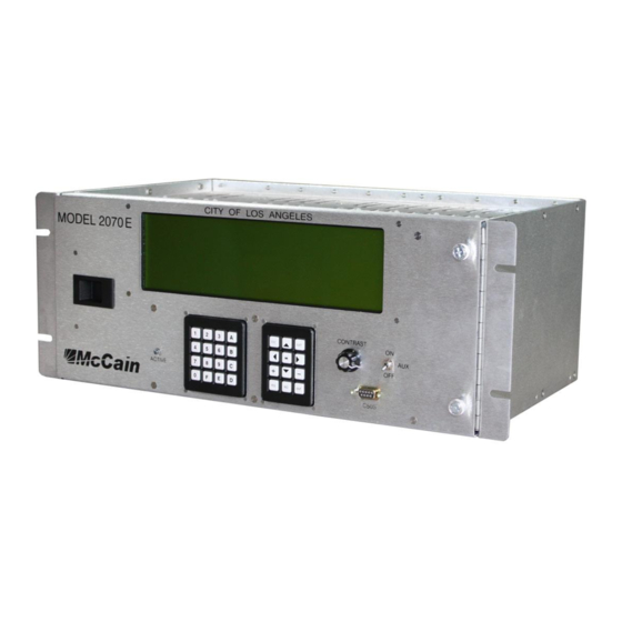
Page 10: Figure 1: 2070E La City Controller, Front And Rear Views
FRONT VIEW REAR VIEW Figure 1: 2070E LA City Controller, Front and Rear Views... -
Page 11: Figure 2: 2070E La City Controller System Configuration
LA CITY LA CITY POWER FIELD I/O SUPPLY C11S C13S COMM LINESYNC ETHERNET LINESYNC C21S POWERUP POWERUP C22S NRESET NRESET SP3 AND SP5 Figure 2: 2070E LA City Controller System Configuration 2070E LA City Controller – User Manual Version 1.0... -
Page 12: Standard Features
1.4 STANDARD FEATURES Operating system Microware Embedded OS-9 Modules (standard, included) 2070-1E LA City CPU Module 2070-2E LA City Field I/O module 2070-3A LA City Front Panel Module 2070-4A LA City Power Supply 2070-7A LA City Asynchronous Serial Communications module. Microprocessors ... -
Page 13: 2070-1E La City Cpu Module
It consists of a Host Board, an Engine Board and a faceplate (plus brackets, standoffs and hardware to fix them to the host board). Figure 3: 2070-1E LA City CPU Module 2070E LA City Controller – User Manual Version 1.0... -
Page 14: Standard Features
2.2 STANDARD FEATURES Processor: Freescale MC68EN360, 32 Bit, 24.576 Mhz, CPU32 Instruction Set. Memory 256Mbit (8 M x 32 Bits) PSRAM (Main RAM) 64Mbit (4 M x 16 Bits) Flash Memory 16Mbit (1 M x 16 Bits) NonVolatile-SRAM ... - Page 15 Async rates (bps): 1200, 2400, 4800, 9600, 19.2k, 38.4k / Optional: 57.6k, 115.2k. Sync rates (bps): 153.6k, 115.2k. Interface pins: SP3_TXD: Transmit Data (O) SP3_RXD: Receive Data (I) SP3_RTS: Request To Send (O) 2070E LA City Controller – User Manual Version 1.0...
- Page 16 SP3_CTS: Clear To Send (I) SP3_CD: Carrier Detect (I) SP3_TXC_INT: Transmit Clock Internal (O) SP3_TXC_EXT: Transmit Clock External (I) SP3_RXC_EXT: Receive Clock External (I) Serial Port 4 (SP-4): Usage: External user interface and general purpose. Location: available at the DIN-96 connector. Operating modes: Asynchronous.
- Page 17 Location: DataKey’s receptacle at Front plate and serial EEPROM on Host Board. Operating modes: Synchronous. Sync rates (bps): Application specific. Interface pins: SPI_MOSI: Master-Out-Slave-In (O) SPI_MISO: Master-In-Slave-Out (I) SPI_CLK: Clock (O) SPI_SEL_1: Select 1 (O) SPI_SEL_2: Select 2 (O) 2070E LA City Controller – User Manual Version 1.0...
-
Page 18: Theory Of Operation
SPI_SEL_3: Select 3 (O) SPI_SEL_4: Select 4 (O) Ethernet Interface (ENET): Usage: Local and Network Communications. Location: Two 10/100BASE-T Ethernet ports on Front plate. Operating modes: Synchronous, Manchester-encoded, Differential. Sync rates (bps): 10M, 100M. The Ethernet switch uses the ports as follow: ENET1P0 to communicate to the Ethernet transceiver (IC2). - Page 19 RS 485 differential signals for the communication ports S1 to SP6, the interruption signals LINESYNC, POWERUP and POWERDN, the Ethernet transmission and reception lines, the +5VDC, +5VSTD and +12VISO, A2 and A3 install lines, and the CPURESET and FPALED lines. 2070E LA City Controller – User Manual Version 1.0...
- Page 20 C13S Connector This is a DB25 connector containing the RS 485 differential line communication signals for the SP8, the external control signals from 2070 power supply also as RS 485 signals and the +5VDCISO power. A2 and A3 Connector Sensor This circuit is used to let know the CPU when the A2 and/or A3 slots on serial motherboard are being used.
- Page 21 /LB and /UB of each memory, this enable inputs are controlled by the lines /(LM-WE) and /(LU-WE) for PSRAM1, and /(UM- WE) and /(UU-WE) for PSRAM2. 2070E LA City Controller – User Manual Version 1.0...
- Page 22 Implemented by a parallel real-time clock with CPU supervisor and external SRAM non-volatile memory backup BQ4845S-A4N and a 32.768KHz external quartz crystal. It is addressed by the address lines A0 to A3, allowing access to the 16 bytes of real-time clock and control registers.
-
Page 23: 2070-1E La City Board Block Diagrams
SP5_RxCLK+ SP5_RxCLK Board (Header) SP5_RxCLK- SP5_TxCLK SP5_TxCLK+ ENET1I2C1SCL I2C1SCL SP5_TxCLK- ENET1I2C1SDA I2C1SDA ENET1SPIQ SPIQ ENET1SPIS_N SPIS_N SP6_RxD+ RS 485 SP6_RxD RESET SP6_RxD- Receiver/Driver SP6_TxD SP6_TxD+ SP6_TxD- Sistem RESET POWERUP RESET Interface 2070E LA City Controller – User Manual Version 1.0... - Page 24 This page was intentionally left blank...
-
Page 25: Connectors' Pin Out
2.6 CONNECTORS’ PIN OUT: C13S Connector (DB25 Female): Function SP8_TxD+ SP8_RxD+ SP8_TxCLK+ SP8_RxCLK+ SP8_RTS+ SP8_CTS+ SP8_DCD+ LINESYNC+ NRESET+ POWERDN+ ISO+5VDC ISOGND SP8_TxD- SP8_RxD- SP8_TxCLK- SP8_RxCLK- SP8_RTS- SP8_CTS- SP8_DCD- LINESYNC- NRESET- POWERDN- FGND 2070E LA City Controller – User Manual Version 1.0... - Page 26 Ethernet Connector, ETH 1/2 (RJ45): ENET 1 Port 3 (Up) Function Unused Unused Unused Unused ENET 1 Port 4 (Down) Function Unused Unused Unused Unused Datakey receptacle connector: Function Ground Data out Chip select Serial clock Data in Data in Serial clock Chip select Data out...
-
Page 27: 2070-1E La City Module Dimensions
Turn off the controller using the power switch located in the front plate of 2070-4A LA City Module. Slide the 2070-1E LA City CPU into slot A5 thru the card guides. Press the module into the backplane and tighten the thumbscrews until the CPU module is secure. 2070E LA City Controller – User Manual Version 1.0... -
Page 28: 2070-2E La City Module, Field I/O Module
“SP-3 ACTIVE” port indicator are located at the front plate. The Field I/O module is optically isolated from the rest of the 2070E LA City Controller. The 2070-2E LA City Field I/O Module consists of: ... -
Page 29: Theory Of Operation
It enables a buffer gate to generate a reset signal that goes to the microprocessor and FLASH memory. It is converted to EIA-485 differential signals and routed to the C12S connector. 2070E LA City Controller – User Manual Version 1.0... - Page 30 LINESYNC: Once the LINESYNC is isolated it is inverted again, then the inverted and not-inverted signals go to the processor. It is converted to EIA-485 differential signals and routed to the C12S connector. POWERDOWN: It is converted to EIA-485 differential signals and routed to the C12S connector. SP-3 and SP-5 Serial ports SP-5 The module receives the SP-5 transmission signals (TxD and TxC) through the A3 connector;...
- Page 31 WDT enable shunt: A watchdog timer enable shunt is provided on the module. It consists of a 3-positions header (JP1) and a jumper to be placed at either ON or OFF position. 2070E LA City Controller – User Manual Version 1.0...
- Page 32 Jumper at ON position (pin-1 to pin-2): The processor outputs a state change on OUTPUT 39 (Monitor Watchdog Timer Input) every 100ms for 10 seconds or due to Set Output Command. The watchdog output is sent to the output port #5 bit 8 and located at C1S connector pin-103. ...
- Page 33 When the clock input is at either the high or low level, the input signals have no effect at the outputs. The parallel output ports’ stage is powered with ISO +5VDC. 2070E LA City Controller – User Manual Version 1.0...
- Page 34 Connectors 150-Positions header This is a 150-pins high density 2mm male header connector used to interconnect the main board (which support all of the input/output, power, isolation and control circuitry) and the connector board (which support all of the necessary connectors for the field interface) that has the mating female receptacle. A3 Connector It is a 96-pin right angle DIN connector used to interface the Field I/O module to the serial mother board.
-
Page 35: 2070-2E La City Block Diagram
RxD+ RxD- RxD- RxCLK+ RxCLK+ RxCLK- RxCLK- RS 485 Isolation RS 485 Receiver/Driver Stage Receiver/Driver TxD+ SP3 LED’S TxD- TxCLK+ TxCLK- RxD+ SP5 LED’S RxD- Switch RxCLK+ Enable/Disable RxCLK- Active LED 2070E LA City Controller – User Manual Version 1.0... - Page 36 This page was intentionally left blank...
-
Page 37: Connectors' Pin Out
SP3 TxCLKO+ SP5 RxCLK- SP3 RxCLK+ SP3 TxD- LINESYNC+ SP3 RxD- NRESET+ SP3 TxCLKO- Connector C1S: Function Function Function Function DCG #2 DCG #2 DCG #2 DET RES O39 WDT DCG #2 2070E LA City Controller – User Manual Version 1.0... - Page 38 Connector C11S: Function Function DCG #2 DCG #2 DCG #2 DCG #2...
-
Page 39: 2070-2E La City Module Dimensions
2. Slide the 2070-2E LA City into slot A3 thru the car guides. Press the module into the backplane; tighten the thumbscrews until the module is secure. These steps complete the 2070-2E LA City installation into the 2070E LA City Controller. 2070E LA City Controller – User Manual... -
Page 40: 2070-7A La City Module, Async Communication Serial Board
4 2070-7A LA CITY MODULE, ASYNC COMMUNICATION SERIAL BOARD 4.1 GENERAL DESCRIPTION The 2070-7A LA City Module is a hot swappable asynchronous serial communication module that extends and isolates the Controller’s serial communication ports available on the serial motherboard slots A1/A2 to the Controller’s rear panel for field connections. -
Page 41: Theory Of Operation
+5VDC isolated power supply for all the related circuitry for C21S and C22S. By using a jumper, the +5VDC isolated power supply can be individually connected to the Pin-9 of the C21S and/or C22S connector. 2070E LA City Controller – User Manual Version 1.0... -
Page 42: 2070-7A La City Block Diagram
4.3 2070-7A LA CITY BLOCK DIAGRAM A2 Connector DIN 96 C21S TxD+ TxD- RxD+ RS 485 Isolation RS 232 RxD- Receiver/Driver Stage Transceiver RTS+ RTS- CTS+ CTS- DCD+ JUMPER Ch. “A” Disable Tx & Rx DCD- PIN 9 +5VDCISO Status LED’s Status LED Jumper Enable/Disable... -
Page 43: Connectors' Pin Out
SP2 RXD SP2 TXD IFC GND SP2 RTS SP2 CTS +5VDC ISO 4.5 THE 2070-7A LA CITY MODULE DIMENSIONS Note: All dimensions are shown in inches. Figure 8: 2070-7A LA City Dimensions 2070E LA City Controller – User Manual Version 1.0... -
Page 44: Adjustment
4.6 ADJUSTMENT The 2070-7A LA City provides two headers for independently enabling/disabling the communications channels. Placing a jumper at “J1” header, the channel 1 (SP-1/SP-3) at C21S is disabled (See figure 9). Placing a jumper at “J2” header, the channel 2 (SP-2/SP-4) at C22S is disabled (See figure 9). Figure 9: Jumpers J1 and J2 The 2070-7A LA City provides two headers for connecting/disconnecting the +5VDC isolated power supply from the front connectors:... -
Page 45: Installing The 2070-7A La City Module
Two thumbscrews for a mechanical attachment to the Chassis unit. A sub-assembly board: contains all necessary circuitry for implementing the FPA functions. A metal panel: provides mechanical support, necessary cutouts and identification. 2070E LA City Controller – User Manual Version 1.0... -
Page 46: Theory Of Operation
The Figure 11 shows the 2070-3A LA City module. Figure 11: 2070-3A LA City Module 5.2 THEORY OF OPERATION Microcontroller The FREESCALE M9S12E64 runs at 24.576MHZ and performs all necessary functions of the Front Panel assembly: communicates to the CPU via the serial asynchronous port SP-6, scans the keypads and displays messages on the LCD display, controls the LCD backlight, generates the BELL signal, monitors the AUX switch and the manual RESET switch. - Page 47 An LED with a series resistor connected to Vcc is activated by the CPU through the P3 connector. This LED is normally used to indicate the status of the application running in the CPU. 2070E LA City Controller – User Manual Version 1.0...
-
Page 48: 2070-3A La City Block Diagram
5.3 2070-3A LA CITY BLOCK DIAGRAM Connector Unit LCD Display Contrast Knob Lines LCD Keyboards CRYSTAL 4x4 & 3x4 MICROCONTROLLER BACKLITE BACKLITE Circuit Auxiliar Switch RESET Switch BUZZER Connector 2070 CPU RESETFP Active FPACTIVELED C50S RS 485 C50 Enable C50RxD+ Transceiver RS 485 C50RxD-... -
Page 49: Connectors' Pin Out
Figure 12: 2070-3A LA City Dimensions 5.6 ADJUSTMENT The only adjustment available on the Front Panel Assembly is the LCD contrast that can be adjusted in accordance with user’s needs through the contrast knob. 2070E LA City Controller – User Manual Version 1.0... -
Page 50: Installing The 2070-3A La City Module
5.7 INSTALLING THE 2070-3A LA CITY MODULE Normally the controller has the 2070-3A LA City assembly, but this section contains information of installation of the 2070-3A LA City in case it is not. 1. Turn off the controller using the power switch located in the front plate of 2070-4A LA City Module. -
Page 51: Theory Of Operation
EMI Filter The EMI filter is contained into a discrete device. It receives the AC input signal and delivers the power already filtered to the circuitry in the Power Supply module. 2070E LA City Controller – User Manual Version 1.0... - Page 52 Power Supply Modules The Power Supply filters the 120 VAC line and then feeds three power modules. These power modules generate the required voltage outputs: +5VDC module, is used for providing +5VDC. +12VDC module, is used for providing +12VDC and -12VDC (the -12VDC are obtained through a switching regulator on control board).
- Page 53 50 ± 1 % duty cycle; it is synchronized to the 60Hz VAC incoming power line at 120 and 300 degree. The LINESYNC signal begins when SYSTEMRESET signal transitions to High; this signal 2070E LA City Controller – User Manual Version 1.0...
- Page 54 continues until SYSRESET transitions to Low. The microprocessor compensates for missing pulses during normal operation. Control signals output stage It is used for supplying the appropriate drive sink capability to the control signals on the PS connectors. This stage consists of two FET’s and three resistors for each control signal, it is arranged for giving an output of the same logic level as the input;...
- Page 55 Unit for two 500ms Power Loss periods occurring in a 1.5 second period. +5 VDC compensates 250 mV total line drop. Remote Sense Open sense load protection provided. Fuse Value: 2 Amps, Type: 3AG 2070E LA City Controller – User Manual Version 1.0...
-
Page 56: 2070-4A La City Block Diagram
6.3 2070-4A LA CITY BLOCK DIAGRAM Conn. 10 Pos. Zero-crossing Isolation Stage AC Monitor 1.- +5 VDC Detection Circuit 2.- +12 VDCSERIAL 3.- -12 VDC SERIAL 4.- DC GND #1 5.- +5 VDC STANDBY 6.- +5 VDC SENSE +5 VDC Stand-by 7.- DC GND SENSE Control Circuitry... -
Page 57: Ps1 And Ps2 Connectors' Pin Out
DC GND #1 (+5 VDC & 12 SERIAL) +5 VDC STANDBY +12 VDC ISO DC GND (+12 VDC ONLY) POWER DOWN / AC FAIL POWER UP / SYS RESET EQUIPMENT GROUND LINESYNC 2070E LA City Controller – User Manual Version 1.0... -
Page 58: 2070-4A La City Module Dimensions
6.5 2070-4A LA CITY MODULE DIMENSIONS Note: All dimensions are shown in inches. Figure 14: 2070-4A LA City Dimensions 6.6 ADJUSTMENT There are four factory set adjustments of the Power Supply module and must not be moved. One adjustment corresponds to the AC line voltage window: ... -
Page 59: Installing The 2070-4A La City Module
Card guides on top and bottom sides to allow modules slide and plug to the serial motherboard and also for installing the power supply module. The hinge on right side and latch on left side to hold and secure the front panel assembly. 2070E LA City Controller – User Manual Version 1.0... -
Page 60: Figure 15: 2070E Chassis Unit
Figure 15: 2070E Chassis unit Chassis front view Chassis rear view Figure 16: Front and rear view 2070E Chassis... -
Page 61: Serial Motherboard
96-pin DIN connectors and to the connector dedicated to the front panel interface. It also carries the serial communication among the dedicated modules and front panel module. Figure 17: 2070 Serial motherboard 2070E LA City Controller – User Manual Version 1.0... -
Page 62: 2070 Serial Motherboard Block Diagram
7.3 2070 SERIAL MOTHERBOARD BLOCK DIAGRAM Connector Connector Connector Connector Connector LINESYNC LINESYNC LINESYNC LINESYNC LINESYNC POWERUP POWERUP POWERUP POWERUP POWERUP POWERDN POWERDN POWERDN POWERDN POWERDN CPU RESET CPU RESET CPU RESET CPU RESET CPU RESET CPU LED CPU LED CPU LED CPU LED CPU LED... -
Page 63: Connectors' Pin Out
SP3RXCI- NETWK2 SP3RXC+ LINESYNC SP3RXC- NETWK3 POWERUP CPURESET NETWK4 POWERDOWN CPU LED DCG#1 DCG#1 DCG#1 +12VDCSERIAL -12VDCSERIAL C28 +5VDCSTANDBY 5VDC +5VDC +5VDC DCG#1 DCG#1 DCG#1 +12VDC +12VDC +12VDC DCG#2 DCG#2 DCG#2 2070E LA City Controller – User Manual Version 1.0... - Page 64 A2 Connector Function Function Function SP1TXD+ SP6TXD+ SP5TXD+ SP1TKD- SP6TXD- SP5TXD- SP1RXD+ SP6RXD+ SP5TXC+ SP1RXD- SP6RXD- SP5TXC- SP1RTS+ SP1TXCO+ SP5RXD+ SP1RTS- SP1TXCO- SP5RXD- SP1CTS+ SP1TXCI+ SP5RXC+ SP1CTS- SP1TXCI- SP5RXC- SP1DCD+ SP1RXC+ SP3TXD+ SP1DCD- SP1RXC- SP3TXD- SP2TXD+ SP4TXD+ SP3RXD+ SP2TXD- SP4TXD- SP3RXD- SP2RXD+ SP4RXD+...
- Page 65 NETWK2 A3INSTALLED SP3RXC+ LINESYNC SP3RXC- NETWK3 POWERUP CPURESET NETWK4 POWERDOWN CPU LED DCG#1 DCG#1 DCG#1 +12VDCSERIAL -12VDCSERIAL C28 +5VDCSTANDBY 5VDC +5VDC +5VDC DCG#1 DCG#1 DCG#1 +12VDC +12VDC +12VDC DCG#2 DCG#2 DCG#2 2070E LA City Controller – User Manual Version 1.0...
- Page 66 A4 Connector Function Function Function SP1TXD+ SP6TXD+ SP5TXD+ SP1TKD- SP6TXD- SP5TXD- SP1RXD+ SP6RXD+ SP5TXC+ SP1RXD- SP6RXD- SP5TXC- SP1RTS+ SP1TXCO+ SP5RXD+ SP1RTS- SP1TXCO- SP5RXD- SP1CTS+ SP1TXCI+ SP5RXC+ SP1CTS- SP1TXCI- SP5RXC- SP1DCD+ SP1RXC+ SP3TXD+ SP1DCD- SP1RXC- SP3TXD- SP2TXD+ SP4TXD+ SP3RXD+ SP2TXD- SP4TXD- SP3RXD- SP2RXD+ SP4RXD+...
- Page 67 NETWK2 A3INSTALLED SP3RXC+ LINESYNC SP3RXC- NETWK3 POWERUP CPURESET NETWK4 POWERDOWN CPU LED DCG#1 DCG#1 DCG#1 +12VDCSERIAL -12VDCSERIAL C28 +5VDCSTANDBY 5VDC +5VDC +5VDC DCG#1 DCG#1 DCG#1 +12VDC +12VDC +12VDC DCG#2 DCG#2 DCG#2 2070E LA City Controller – User Manual Version 1.0...
- Page 68 Front Panel Connector Function Function SP4TXD+ SP4TXD- SP4RXD+ SP4RXD- SP6TXD+ SP6TXD- SP6RXD+ SP6RXD- DCG#1 DCG#1 +12VDCSERIAL -12VDCSERIAL DCG#1 DCG#1 CPU LED DCG#1 CPURESET DCG#1 DCG#1 C50ENABLE DCG#1 +5VDC +5VDC +5VDC +5VDC +5VDC PS2 Connector Function Function +5VDC DCG#2 +12VDCSERIAL POWERDOWN -12VDCSERIAL POWERUP EQUIPMENT...
-
Page 69: General Specifications
+12.0 VDC Serial: 0.1 A - 0.5 A –12.0 VDC Serial: 0.1 A - 0.5 A +12.0 VDC ISO: 0.1 A - 1.0 A Environment: Operating Temperature: -37° C to +74° C Humidity: 0 to 95% (non-condensing) 2070E LA City Controller – User Manual Version 1.0...
Need help?
Do you have a question about the 2070E LA CITY and is the answer not in the manual?
Questions and answers