
Related Manuals for McCain ATC ex 2070N2


Summary of Contents for McCain ATC ex 2070N2
- Page 1 Version: 1.2 Product Part Number: M46794, M54111 Product specifications: www.mccain-inc.com Customer support: support@mccain-inc.com Product Inquiries: 888-2-McCain (888-262-2246)
- Page 2 This page was intentionally left blank...
- Page 3 Version REVISIONS Date Comments G. Rubio 2/21/2013 Initial Release T. Reddan 6/10/2013 Manual photo and product naming conventions updated R McAlpine 05/13/2015 Added M54111 part number, general formatting updates...
- Page 4 McCain Inc. shall not be liable for errors contained herein or for incidental or consequential damages in connection with furnishing, performance or use of this material. MCCAIN MAKES NO WARRANTY OF ANY KIND WITH REGARD TO THIS MATERIAL, INCLUDING, BUT NOT LIMITED TO, THE IMPLIED WARRANTIES OF MERCHANTABILITY AND FITNESS FOR A PARTICULAR PURPOSE.
-
Page 5: Table Of Contents
General Description ........................38 Theory of Operation ........................39 2070-7A Block Diagram ......................40 Connectors’ Pin Out: ........................41 The 2070-7A module dimensions: ....................41 Adjustment ..........................42 Installing the 2070-7A Module ..................... 43 ATC eX 2070N2 Controller – User Manual Version 1.2... - Page 6 2070-3B MODULE, FRONT PANEL ASSEMBLY .............. 44 General Description ........................44 Theory of Operation ........................45 2070-3B Block Diagram ......................47 Connectors’ Pin Out ........................48 The 2070-3B module dimensions: ....................48 Adjustment ..........................49 Installing the 2070-3B Module ..................... 49 2070-4N(A) POWER SUPPLY MODULE ................
- Page 7 TABLE OF FIGURES Figure 1: ATC eX 2070N2 Controller, Front and Rear Views ............... 2 Figure 2: ATC eX 2070N2 Controller System Configuration ................ 3 Figure 3: 2070ATC CPU Module ........................5 Figure 4: 2070ATC CPU Module: Host Board and Engine Board ..............7 Figure 5: 2070ATC CPU Module Dimensions ....................
- Page 8 This page was intentionally left blank...
-
Page 9: Atc Ex 2070N2 Controller
(Advanced Transportation Controller) 5.2b standards and Caltrans Transportation Electrical Equipment Specifications (TEES) 2009 and Errata 1 January 21, 2010. The McCain’s ATC eX 2070N2 Controller’s primary function is intersection control but can be used for a multitude of applications based on the controller’s software. -
Page 10: Configuration
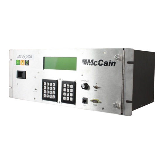
2070-3B Front Panel module. 2070-4N (A) Power Supply module. 2070-7A Asynchronous Serial Communications module. Blank filler plates: There are four 2X and one 1X. Front View Rear View Figure 1: ATC eX 2070N2 Controller, Front and Rear Views... -
Page 11: Figure 2: Atc Ex 2070N2 Controller System Configuration
Figure 2: ATC eX 2070N2 Controller System Configuration ATC eX 2070N2 Controller – User Manual Version 1.2... -
Page 12: Standard Features
1.4 Standard Features Operating system Linux, Version 2.6.22 Modules (standard, included) 2070ATC CPU Module 2070-2N Field I/O module 2070-3B LCD/Front Panel Module 2070-4N(A) Power Supply 2070-7A Asynchronous Serial Communications module. Microprocessors MPC8360E Freescale PowerQUICC II Pro microprocessor Backup real-time clock (RTC) ... -
Page 13: 2070Atc Cpu Module
The 2070ATC CPU is available with McCain’s user-friendly, NTCIP compliant Omni eX intersection control software. This advanced software features a comprehensive ‘Help’ feature to support technicians in the field. The software supports all NEMA and NTCIP standard controller functions as well as a number of enhanced features for maximum flexibility. -
Page 14: Standard Features
2.2 Standard Features Operating System: Linux, Version 2.6.22 Microprocessor: MPC8360E Freescale PowerQUICC II Pro communications processor Backup real-time clock (RTC): Maxim DS1390 Memory: 16MB Flash memory 128MB DDR RAM (expandable) 2MB non-volatile SRAM Communication interfaces: Two SDLC ports ... -
Page 15: Theory Of Operation
The Host board and Engine board are shown in Error! Reference source not found.. These two major assemblies are explained below in separated sections. Figure 4: 2070ATC CPU Module: Host Board and Engine Board ATC eX 2070N2 Controller – User Manual Version 1.2... -
Page 16: Communication Interface Descriptions
2.4 Communication Interface Descriptions Serial Port 1 (SP-1): Usage: This is a general purpose port. Location: available at the DIN-96 connector. Operating modes: Asynchronous, Synchronous, HDLC, SDLC. Async rates (bps): 1200, 2400, 4800, 9600, 19.2k, 38.4k / Optional: 57.6k, 115.2k. Sync rates (bps): 19.2k, 38.4k, 57.6k, 76.8k, 153.6k. - Page 17 SP3_RTS: Request To Send (O) SP3_CTS: Clear To Send (I) SP3_CD: Carrier Detect (I) SP3_TXC_INT: Transmit Clock Internal (O) SP3_TXC_EXT: Transmit Clock External (I) SP3_RXC_EXT: Receive Clock External (I) ATC eX 2070N2 Controller – User Manual Version 1.2...
- Page 18 Serial Port 4 (SP-4): Usage: External user interface and general purpose. Location: available at the DIN-96 connector. Operating modes: Asynchronous. Async rates (bps): 1200, 2400, 4800, 9600, 19.2k, 38.4k / Optional: 57.6k, 115.2k Interface pins: SP4_TXD: Transmit Data (O) ...
- Page 19 SPI_MOSI: Master-Out-Slave-In (O) SPI_MISO: Master-In-Slave-Out (I) SPI_CLK: Clock (O) SPI_SEL_1: Select 1 (O) SPI_SEL_2: Select 2 (O) SPI_SEL_3: Select 3 (O) SPI_SEL_4: Select 4 (O) ATC eX 2070N2 Controller – User Manual Version 1.2...
- Page 20 Universal Serial Bus (USB) Port: Usage: Facilitate the transfer of data files to/from the CPU by using USB memory devices as an alternative to laptop computer. Location: Two USB connectors at Front plate. Requirements: Hardware and Software conforms to v2.0 USB devices to be used are formatted as FAT16 file system providing a 2GB storage.
-
Page 21: Host Board
Once received these signals are routed to the Engine Board through the P2 connector. Also, these signals are inverted, isolated (POWERUP is ORed with CPULRESET at this stage to generate the RESET signal), converted to differential line signals and then routed to C13S connector. ATC eX 2070N2 Controller – User Manual Version 1.2... - Page 22 Receptacles for engine board installation P1 and P2 are the two 50-position receptacle connectors that provide an interface between the Engine board and Host board, they carry the RS-485 differential signals for the serial communication ports SP-1, SP-2, SP-3, SP-4, SP-5, SP-6, and SP-8; for the SPI bus, also the CPU_ACTIVE LED, Ethernet, DATAKEY and USB lines, +5VSTANDBY and interruption signals LINESYNC, POWERUP and POWERDOWN.
- Page 23 Engine Board through the other common cathode dual diode. ATC eX 2070N2 Controller – User Manual Version 1.2...
- Page 24 Ethernet switches The Host Board provides two, Layer 2, managed switches with auto-switching capability for both 10BASE-T and 100BASE-T systems. Each switch provides five Ethernet transceivers; all PHY units support 10BASE-T and 100BASE-TX. In addition, two of the PHY units support 100BASE-FX (port 4 and port 5). Each switch is connected to an independent Ethernet port coming from the Engine Board called ENET1 and ENET2.
- Page 25 This circuit is comprised of a NPN transistor, a limiting resistor for base current and a pull-up resistor connected to +5VDC at the collector. The FPALED signal is at +5VDC while the transistor is deactivated and at logic ground when activated. ATC eX 2070N2 Controller – User Manual Version 1.2...
-
Page 26: Engine Board
A2-A3 installation detection circuitry This circuit is used to let the CPU know when the A2 and/or A3 slots on serial motherboard have installed a 2070 type card. The circuitry consists of two inverter gates with the inputs to a pull-up and connected to the sensing lines on A5 connector, these two lines come from the A2 and A3 slot connectors on serial motherboard. - Page 27 One local I2C bus for interfacing to the Boot EEPROM. One BDM bus for allowing the programming. Monitors and sets the status of important input/output signals (Power up, Power down, Linesync, Datakey present, CPU Active, CPU Reset, etc.). ATC eX 2070N2 Controller – User Manual Version 1.2...
- Page 28 Reset management The Engine Board provides an active-low, +5VDC, output signal called CPU_RESET. It is used to reset other internal/external system devices. This output signal is generated by the CPU Reset line circuit. This circuit acts as an OR gate that receives two input signals, both are provided by the Processor, one input signal is related to a hardware reset and the other one to a software reset.
- Page 29 The KS8721 transceiver’s purpose is physical; it implements the hardware functions for sending and receiving the Ethernet frames; it handles the line modulation at one side and the binary packet signaling at the other side. ATC eX 2070N2 Controller – User Manual Version 1.2...
- Page 30 The interface consists of data signals, management signals and an interrupt signal to alert the Processor of status change at the physical layer. MII (Media Independent Interface) is set by default mode after power-up. The MII bus transfers data using 4-bit words (nibble) in each direction (4 transmit data bits, 4 receive data bits).
- Page 31 “hiccup” protection. It also ensures a smooth and controlled start-up supporting pre-biased outputs. ATC eX 2070N2 Controller – User Manual Version 1.2...
- Page 32 Memory and peripherals’ power source The Memory and peripherals’ power source is based on the LM5642X Dual Synchronous Buck Converter in a typical two channel application circuit. This converter consists of two current mode synchronous buck regulator controllers operating 180° out of phase with each other at a normal switching frequency of 375 kHz.
- Page 33 There are some pins at the 50-position connectors on both Engine Board and Host Board that are not used; in accordance with the 5.2b specification these pins are reserved for future enhancements. ATC eX 2070N2 Controller – User Manual Version 1.2...
-
Page 34: 2070Atc Hostboard And Engine Board Block Diagrams
2.5 2070ATC Hostboard and Engine Board Block Diagrams P2 Connector Connector DIN 96 RxCLK TxCLKI TxCLKO P1 Connector RxCLK TxCLKI TxCLKO Power Control Power Control RxCLK USB 2.0 Switch Switch TxCLK Controller Overcurrent USB_PSWITCH Overcurrent Overcurrent Pswitch USB_OVERCURRENT Pswitch Pswitch RxCLK VBUSPWR TxCLKI... - Page 35 ENET1 PORT3 LED1_0/2 ENET2 PORT1 EEPROM VDAR 1.2 VDC VDDC Power Supply ENET1I2C1SCL ENET1I2C1SDA 3.3 VDC VDDIO USB Programing Power Supply VDDAT Board ENET1I2C1SCL I2C1SCL ENET1I2C1SDA I2C1SDA ENET1SPIQ SPIQ ENET1SPIS_N SPIS_N RESET ATC eX 2070N2 Controller – User Manual Version 1.2...
- Page 36 Engine Board Block...
-
Page 37: Connectors' Pin Out
SP8_DCD+ LINESYNC+ NRESET+ POWERDN+ ISO+5VDC ISOGND SP8_TxD- SP8_RxD- SP8_TxCLK- SP8_RxCLK- SP8_RTS- SP8_CTS- SP8_DCD- LINESYNC- NRESET- POWERDN- Chassis GND USB Connector: Function Data - Data + DOWN Function Data - Data + ATC eX 2070N2 Controller – User Manual Version 1.2... - Page 38 Ethernet Connector, ETH 1/1 (RJ45): ENET 1 Port 2 (Up) Function Unused Unused Unused Unused ENET 1 Port 1 (Down) Function Unused Unused Unused Unused Ethernet Connector, ETH 1/2 (RJ45): ENET 2 Port 1 (Up) Function Unused Unused Unused Unused ENET 1 Port 3 (Down) Function Unused...
- Page 39 Datakey receptacle connector: Function Ground Data out Chip select Serial clock Data in Data in Serial clock Chip select Data out Ground LOFO LOFO ATC eX 2070N2 Controller – User Manual Version 1.2...
-
Page 40: Dimensions
2.7 Dimensions The 2070ATC CPU Module has the following dimensions: Figure 5: 2070ATC CPU Module Dimensions 2.8 Adjustment The 2070ATC CPU module has no adjustments to be applied. 2.9 Installing the 2070ATC CPU Module Follow these steps to complete the 2070ATC CPU module installation into the Controller. Turn off the controller using the power switch located in the front plate of 2070-4N (A) Module. -
Page 41: 2070-2N Module, Field I/O Module
A 2070 Type board Contains all necessary circuitry for implementing the 2070-2N functions. A 4X face plate: Provides mechanical support and identification in the Controller. Figure 6: 2070-2N Module ATC eX 2070N2 Controller – User Manual Version 1.2... -
Page 42: Theory Of Operation
3.2 Theory of Operation. The 2070-2N module isolates the Serial port 3 in order to be used at C15S connected. The power for the C13S circuitry (RS-485 devices and opto-isolators) comes from a +5VDC regulator that is fed by the +12VDC ISO. -
Page 43: 2070-2N Block Diagram
AC Line Isolation Microprocessor NRESET POWER UP Stage/OR Reset Circuit CPURESET “A” FAULT M. Connector Isolation LINESYNC LINESYNC Stage POWERDN CS0 WE OE RESET Data Bus Address Bus FLASH ISO POWERDN ATC eX 2070N2 Controller – User Manual Version 1.2... -
Page 44: Connectors' Pin Out
3.4 Connectors’ Pin Out 10 Pin connector A: Function Function Function AC Neutral F. Monitor AC Line ISOGND Chassis GND Connector C15S (DB15 Female): Function Function Function SP3TXD+ DCG #2 SP3TXC- EG (Equipment DCG #2 SP3RXC+ Ground) SP3TXC+ DCG #2 SP3RXD- DCG #2 SP2TXD-... -
Page 45: 2070-2N Field I/O Dimensions
2. Plug the power cord of 2070-4N (A) power supply into NEMA 5-15 receptacle. These steps complete the 2070-2N installation into the ATC eX 2070N2 controller. ATC eX 2070N2 Controller – User Manual... -
Page 46: 2070-7A Module, Async Communication Serial Board
2070-7A MODULE, ASYNC COMMUNICATION SERIAL BOARD 4.1 General Description The 2070-7A Module is a hot swappable asynchronous serial communication module that extends and isolates the Controller’s serial communication ports available on the serial motherboard slots A1/A2 to the Controller’s rear panel for field connections. The module provides two 9-positions D-sub female connectors on the face plate, C21S as channel 1 and C22S as channel 2. -
Page 47: Theory Of Operation
+5VDC isolated power supply for all the related circuitry for C21S and C22S. By using a jumper, the +5VDC isolated power supply can be individually connected to the Pin-9 of the C21S and/or C22S connector. ATC eX 2070N2 Controller – User Manual Version 1.2... -
Page 48: 2070-7A Block Diagram
4.3 2070-7A Block Diagram A2 Connector DIN 96 C21S TxD+ TxD- RxD+ RS 485 Isolation RS 232 RxD- Receiver/Driver Stage Transceiver RTS+ RTS- CTS+ CTS- DCD+ JUMPER Ch. “A” Disable Tx & Rx DCD- PIN 9 +5VDCISO Status LED’s Status LED Jumper Enable/Disable C22S... -
Page 49: Connectors' Pin Out
Function SP2 DCD SP2 RXD SP2 TXD ISO GND SP2 RTS SP2 CTS +5VDC ISO 4.5 The 2070-7A module dimensions: Note: All dimensions are shown in inches. Figure 9: 2070-7A Dimensions ATC eX 2070N2 Controller – User Manual Version 1.2... -
Page 50: Adjustment
4.6 Adjustment The 2070-7A provides two headers for independently enabling/disabling the communications channels. Placing a jumper on the “J1” header, disables channel 1 (SP-1/SP-3) at C21S (See figure 6). Placing a jumper on the “J2” header, disables channel 2 (SP-2/SP-4) at C22S (See figure 6). Figure 10: Jumpers J1 and J2 The 2070-7A provides two headers for connecting/disconnecting the +5VDC isolated power supply from the front connectors:... -
Page 51: Installing The 2070-7A Module
These steps complete the 2070-7A installation into the Controller. The 2070-7A Module is a hot swappable module because it can be installed and removed while the controller is working without damage to the circuitry. ATC eX 2070N2 Controller – User Manual Version 1.2... -
Page 52: 2070-3B Module, Front Panel Assembly
2070-3B MODULE, FRONT PANEL ASSEMBLY 5.1 General Description The Front Panel Assembly (FPA) provides a user interface via keypads and the LCD display. The module has serial port SP-4 available through the C50S and C50J connectors for a terminal’s connection. Also an ACTIVE LED to show the application’s status, an AUX switch and a LCD’s contrast knob are available. -
Page 53: Theory Of Operation
RS-485 transceiver that handle the SP-4 communication. While the driver’s input is high, the enable inputs disable the SP-4 communications and the C50 enable signal drives high, this signal is one of the differential outputs and it is routed to P3 connector. ATC eX 2070N2 Controller – User Manual Version 1.2... - Page 54 Bell It is an electronic bell controlled by the microcontroller used to signal receipt of ^G (hex 07) and RESET condition. It is performed by a buzzer which is managed by the microcontroller applying a 2 KHz square signal for a period of 350mS. AUX Switch This is a toggle switch that forces the status of the STOP TIME line from microcontroller Low by connecting a pull-up to logic ground.
-
Page 55: 2070-3B Block Diagram
Auxiliar Switch RESET Switch Active BUZZER Connector 2070 CPU C50J RJ45 RESETFP C50 Enable FPACTIVELED C50S RS 485 C50 Enable C50RxD+ Transceiver C50RxD- RS 485 C50TxD+ Transceiver RS 232 C50RxD- Receiver/Driver ATC eX 2070N2 Controller – User Manual Version 1.2... -
Page 56: Connectors' Pin Out
5.4 Connectors’ Pin Out Connector C50S (DB9 Female): Function C50 Enable SP4 RxD SP4 TxD DCG #1 Connector C50J (RJ45): Function C50 Enable SP4 RxD SP4 TxD DCG #1 5.5 The 2070-3B module dimensions: Note: All dimensions are shown in inches. Figure 13: 2070-3B Dimensions... -
Page 57: Adjustment
3. Tighten the thumbscrews until the module is secure. 4. Insert the 40-position ribbon plug connector from the Serial motherboard into the P3 Connector. 5. Make sure the 2070-3B is correctly opened, closed and secured. ATC eX 2070N2 Controller – User Manual Version 1.2... -
Page 58: 2070-4N(A) Power Supply Module
2070-4N(A) POWER SUPPLY MODULE 6.1 General Description The model 2070-4N (A) is the Power Supply module of the Controller. It receives the AC line through the AC cord and provides all necessary power outputs and signal outputs at PS1 and PS2 connectors. The power lines are +5VDC @ 10A, +/-12VDC @ 0.5A, isolated +12VDC @ 1A and the +5VDC Standby power;... -
Page 59: Theory Of Operation
In order to preserve the isolation between the AC and DC signals, a transformer, a diode bridge and an electrolytic capacitor are used to generate 24VDC and feed the circuitry. Also, two opto-isolators MOC8102 are used to isolate the outputs from the AC side to the logic side. ATC eX 2070N2 Controller – User Manual Version 1.2... - Page 60 The AC+ line is separated through two resistor networks in order to attenuate it and also to generate a difference on AC voltage levels, and then the AC signal is feed to the inputs of the voltage monitor device as follow: ...
- Page 61 The LED DC POWER Indicator indicates that the required DC Voltage meets the specified conditions. For the +5VDC, +12VDC and -12VDC supplies, the circuit consists of an LED in series with a 220 Ohms resistor, connected to +3.3VDC and activated by the microcontroller. ATC eX 2070N2 Controller – User Manual Version 1.2...
- Page 62 For the +12VDCISO supply, a discrete voltage monitor device is used. It monitors and indicates if the level is within range. In this case there is an LED with a 2.2KOhms series resistor connected to +12VDCISO and activated by this device. Standby Power The +5VDC STANDBY POWER is provided to hold up system devices during a power down period.
-
Page 63: 2070-4N(A) Block Diagram
10.- EQUIPMENT GND Output stage 11.- LINESYNC 12.- NA -12 VDC Power Voltage Divider Supply Voltage Status LED’s Indicators +5 VDC +12 VDC -12 VDC +12 VDCISO +12 VDCISO +12 VDCISO Module Monitor ATC eX 2070N2 Controller – User Manual Version 1.2... -
Page 64: Ps1 And Ps2 Connectors' Pin Out
6.4 PS1 and PS2 Connectors’ Pin Out PS1 Connector Function +5 VDC +12 VDC SERIAL -12 VDC SERIAL DC GND #1 (+5 VDC & 12 SERIAL) +5 VDC STANDBY +5 VDC SENSE DC GROUND SENSE AC FAIL (VME) SYSRESET (VME) PS2 Connector Function +5 VDC... -
Page 65: 2070-4N(A) Module Dimensions
6.5 2070-4N(A) Module Dimensions Note: All dimensions are shown in inches. Figure 15: 2070-4N (A) Dimensions ATC eX 2070N2 Controller – User Manual Version 1.2... -
Page 66: Adjustment
6.6 Adjustment There are four factory set adjustments of the Power Supply module and must not be moved. One adjustment corresponds to the AC line voltage window: Power Fail: 85VAC ±2VAC. Power Recovery: 90VAC ±2VAC. This is done via a potentiometer located at the edge of the control board. One adjustment is performed for each power module to be set at the DC voltage level required. -
Page 67: Chassis Unit
The hinge on right side and latch on left side to hold and secure the front panel assembly. Figure 16: 2070E Chassis unit ATC eX 2070N2 Controller – User Manual Version 1.2... -
Page 68: Figure 17: Front And Rear View 2070E Chassis
Chassis front view Chassis rear view Figure 17: Front and rear view 2070E Chassis... -
Page 69: Serial Motherboard
96-pin DIN connectors and to the connector dedicated to the front panel interface. It also carries the serial communication among the dedicated modules and front panel module. Figure 18: 2070 Serial motherboard ATC eX 2070N2 Controller – User Manual Version 1.2... -
Page 70: 2070 Serial Motherboard Block Diagram
7.3 2070 Serial Motherboard Block Diagram Connector Connector Connector Connector Connector LINESYNC LINESYNC LINESYNC LINESYNC LINESYNC POWERUP POWERUP POWERUP POWERUP POWERUP POWERDN POWERDN POWERDN POWERDN POWERDN CPU RESET CPU RESET CPU RESET CPU RESET CPU RESET CPU LED CPU LED CPU LED CPU LED CPU LED... -
Page 71: Connectors' Pin Out
SP3RXCI- NETWK2 SP3RXC+ LINESYNC SP3RXC- NETWK3 POWERUP CPURESET NETWK4 POWERDOWN CPU LED DCG#1 DCG#1 DCG#1 +12VDCSERIAL -12VDCSERIAL C28 +5VDCSTANDBY 5VDC +5VDC +5VDC DCG#1 DCG#1 DCG#1 +12VDC +12VDC +12VDC DCG#2 DCG#2 DCG#2 ATC eX 2070N2 Controller – User Manual Version 1.2... - Page 72 A2 Connector Function Function Function SP1TXD+ SP6TXD+ SP5TXD+ SP1TKD- SP6TXD- SP5TXD- SP1RXD+ SP6RXD+ SP5TXC+ SP1RXD- SP6RXD- SP5TXC- SP1RTS+ SP1TXCO+ SP5RXD+ SP1RTS- SP1TXCO- SP5RXD- SP1CTS+ SP1TXCI+ SP5RXC+ SP1CTS- SP1TXCI- SP5RXC- SP1DCD+ SP1RXC+ SP3TXD+ SP1DCD- SP1RXC- SP3TXD- SP2TXD+ SP4TXD+ SP3RXD+ SP2TXD- SP4TXD- SP3RXD- SP2RXD+ SP4RXD+...
- Page 73 NETWK2 A3INSTALLED SP3RXC+ LINESYNC SP3RXC- NETWK3 POWERUP CPURESET NETWK4 POWERDOWN CPU LED DCG#1 DCG#1 DCG#1 +12VDCSERIAL -12VDCSERIAL C28 +5VDCSTANDBY 5VDC +5VDC +5VDC DCG#1 DCG#1 DCG#1 +12VDC +12VDC +12VDC DCG#2 DCG#2 DCG#2 ATC eX 2070N2 Controller – User Manual Version 1.2...
- Page 74 A4 Connector Function Function Function SP1TXD+ SP6TXD+ SP5TXD+ SP1TKD- SP6TXD- SP5TXD- SP1RXD+ SP6RXD+ SP5TXC+ SP1RXD- SP6RXD- SP5TXC- SP1RTS+ SP1TXCO+ SP5RXD+ SP1RTS- SP1TXCO- SP5RXD- SP1CTS+ SP1TXCI+ SP5RXC+ SP1CTS- SP1TXCI- SP5RXC- SP1DCD+ SP1RXC+ SP3TXD+ SP1DCD- SP1RXC- SP3TXD- SP2TXD+ SP4TXD+ SP3RXD+ SP2TXD- SP4TXD- SP3RXD- SP2RXD+ SP4RXD+...
- Page 75 NETWK2 A3INSTALLED SP3RXC+ LINESYNC SP3RXC- NETWK3 POWERUP CPURESET NETWK4 POWERDOWN CPU LED DCG#1 DCG#1 DCG#1 +12VDCSERIAL -12VDCSERIAL C28 +5VDCSTANDBY 5VDC +5VDC +5VDC DCG#1 DCG#1 DCG#1 +12VDC +12VDC +12VDC DCG#2 DCG#2 DCG#2 ATC eX 2070N2 Controller – User Manual Version 1.2...
- Page 76 Front Panel Connector Function Function SP4TXD+ SP4TXD- SP4RXD+ SP4RXD- SP6TXD+ SP6TXD- SP6RXD+ SP6RXD- DCG#1 DCG#1 +12VDCSERIAL -12VDCSERIAL DCG#1 DCG#1 CPU LED DCG#1 CPURESET DCG#1 DCG#1 C50ENABLE DCG#1 +5VDC +5VDC +5VDC +5VDC +5VDC PS2 Connector Function Function +5VDC DCG#2 +12VDCSERIAL POWERDOWN -12VDCSERIAL POWERUP EQUIPMENT...
-
Page 77: General Specifications
+12.0 VDC Serial: 0.1 A - 0.5 A –12.0 VDC Serial: 0.1 A - 0.5 A +12.0 VDC ISO: 0.1 A - 1.0 A Environment: Operating Temperature: -37° C to +74° C Humidity: 0 to 95% (non-condensing) ATC eX 2070N2 Controller – User Manual Version 1.2...
Need help?
Do you have a question about the ATC ex 2070N2 and is the answer not in the manual?
Questions and answers