Advertisement
DESCRIPTION
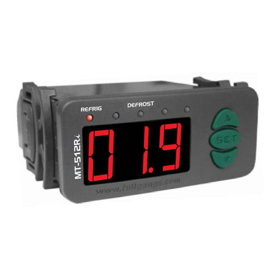
The MT-512Ri is a temperature controller and gauge, with adjustable settings for cooling and defrosting processes. It controls cooling and defrost by stopping the compressor. The controller uses an intelligent system to lock the keys and deactivate the control functions.
Product complies with CE (European Union), NSF (United States) and UL Inc. (United States and Canada).
APPLICATIONS
- Counters
- Cooled chambers
TECHNICAL SPECIFICATION
- Power supply: MT-512Ri → 115 or 230 Vac ±10%(50/60 Hz)
MT-512RiL → 12 or 24 Vac/dc - Control temperature: -50 to 105ºC (-58 to 221°F) (*)
- Maximum current: NO → 16(8)A/250Vac 1HP
NC → 8A/250Vac - Dimensions: 71 x 28 x 71mm
- Operating temperature: 0 to 50 ºC / 32 to 122°F
- Operating humidity: 10 to 90% RH (without condensation)
(*) This instrument can measure and control up to 200ºC temperatures, since used with silicone cable sensor (ex.: SB59).
CLASSIFICATION ACCORDING TO IEC60730-2-9 STANDARD:
- Temperature limit of the installation surface: 50°C / 122°F
- Type of construction: Built-in electronic controller
- Automatic action: Type 1
- Control of pollution: Level 2
- Impulse voltage: 1,5kV
- Temperature for the test of sphere pressure: 75°C and 125°C / 167°F and 257°F
- Insulation: Class II
CONFIGURATIONS
Control temperature adjust (SETPOINT)
- Press
![]() for 2 seconds until appears
for 2 seconds until appears ![]() , and then release the key.
, and then release the key.
The set control temperature will appear. - Use the
![]() or
or ![]() keys in order to change the value and, when ready, press
keys in order to change the value and, when ready, press ![]() to record.
to record.
 , and then release the key.
Parameters table
Configuration parameters protected by access code.
| CELSIUS | FAHRENHEIT | ||||||||
| Fun | Description | Min | Max | Unit | Standard | Min | Max | Unit | Standard |
 | Access code: 123 (one hundred and twenty three) | - | - | - | - | - | - | - | - |
 | Indication offset | -5.0 | 5.0 | °C | 0 | -9 | 9 | °F | 0 |
 | Minimum setpoint allowed for the end user | -50 | 200 | °C | -50 | -58 | 392 | °F | -58 |
 | Maximum setpoint allowed for the end user | -50 | 200 | °C | 75.0 | -58 | 392 | °F | 167 |
 | Control differential (hysteresis) | 0.1 | 20.0 | °C | 1.0 | 1 | 40 | °F | 2 |
 | Delay in restarting the cooling operation | 0 | 999 | sec. | 20 | 0 | 999 | sec. | 20 |
 | Cooling time | 1 | 999 | min. | 240 | 1 | 999 | min. | 240 |
 | Defrosting time (*) | 0 | 999 | min. | 30 | 0 | 999 | min. | 30 |
 | Initial state when turning the device on again | 0- cooling | 1-defrost | - | 0- cooling | 0- cooling | 1-defrost | - | 0- cooling |
 | Indication of the temperature locked during defrost (**) | 0-no | 1-yes | - | 0-no | 0-no | 1-yes | - | 0-no |
 | Delay on the activation of the instrument | 0 | 240 | min. | 0 | 0 | 240 | min. | 0 |
 | Additional time at the end of the first cycle | 0 | 240 | min. | 0 | 0 | 240 | min. | 0 |
 | Situation of the compressor with the damaged sensor | 0-off | 1-on | - | 0-off | 0-off | 1-on | - | 0-off |
 | Intensity of the digital filter (***) | 0 | 9 | - | 0 | 0 | 9 | - | 0 |
 | Time to Key blocker | 14-no | 60 | sec. | 14-no | 14-no | 60 | sec. | 14-no |
 | Deactivation of the control functions | 0 | 2 | - | 0 | 0 | 2 | - | 0 |
* Heating operation mode - To make the instrument work in heating operation mode, simply adjust the F08 function with minimum value until [Hot] appears.
** Frozen indication on display - If F10 is enabled, the indication is only released in the next cooling cycle after the temperature reaches that "locked" value again or after 15 minutes in refrigeration (as security).
*** This filter aims at simulating an increase of the mass of sensor, thus increasing its response time (thermal inertia). The larger the value adjusted in this function, the longest the response time of sensor.
A typical application requiring this filter is the freezer for ice cream or frozen goods, because when the door is opened a hot air mass reaches the sensor directly, causing the indication of the measured temperature to rise quickly and the compressor to be activated unnecessarily many times.
Parameters alteration
- Access function "F01" by simultaneously pressing keys
![]() and
and ![]() for 2 seconds.
for 2 seconds.
When the message![]() appears release the keys, when the indication
appears release the keys, when the indication ![]() appears on the display press the
appears on the display press the ![]() key and use
key and use ![]() or
or ![]() to enter the access code (123) When ready press the
to enter the access code (123) When ready press the ![]() button to confirm.
button to confirm. - If the keys are locked, the controller will show the message
![]() in the display upon pressing the
in the display upon pressing the ![]() or
or ![]() key and will not permit any change in value
key and will not permit any change in value - Use keys
![]() or
or ![]() to access the desired function.
to access the desired function. - After selecting the function, press
![]() (press once quickly) to view the value configured for that function.
(press once quickly) to view the value configured for that function. - Use the
![]() or
or ![]() keys to change the value and, when ready, press
keys to change the value and, when ready, press ![]() to memorize the configured value and return to the function menu.
to memorize the configured value and return to the function menu. - To exit the menu and return to the normal operation (temperature indication), press
![]() (hold it in) until
(hold it in) until ![]() appears.
appears.
 appears release the keys, when the indication
  appears.
 FUNCTIONS WITH FACILITATED ACCESS
Maximum and minimum temperature logs
Press the  key. The minimum and maximum temperatures registered will appear.
Note: To restart the logs you just have to keep the key pressed during the viewing of the minimum and maximum temperatures until  to be displayed.
Manual Defrost
- To change from "cooling" to "defrost" or vice-versa, irrespective of the programming, hold
![]() key in for four seconds, until
key in for four seconds, until ![]() or
or ![]() appears in the diplay.
appears in the diplay.
Processes Viewing
To visualize the status and the elapsed time, press  .
.
 → Initial delay,
  → Refrigeration,
  → Defrosting.
If the control functions are turned off, the  will work as a simple temperature gauge, without controlling the cooling and defrost. Therefore, the status and the time elapsed will not be displayed.
Key blocking
For security reasons this controller permits blocking the key settings.
With this feature enabled, the setpoint and further settings are protected against undue alterations. After key blocking, the user can only see the setpoint and settings, when trying to change the settings the controller will display the message  .
.
To proceed with the key blocking it is required that the parameter "F15 -Time to key Blocker" is configured with a different value than" 14-No " (15-60 seconds).
If F15 is set as "No" the key lock is not allowed.
To block, hold the key for the time programmed in function F15.
The controller will display the message +  .
.
To unblock, turn off the controller and turn it back on holding the key for 10 seconds untill the message +  be displayed..
Deactivation of the control functions
When the control functions are turned off, the controller starts to operate as a temperature gauge only and the output switch is turned off.
The method used to turn off the control functions depends on the configuration of the parameter "F16- Deactivation of the control functions":
 | Does not allow the control functions to be turned off; |
 | Allows the control functions to be turned on and off only if the keys are not locked; |
 | Allows the control functions to be turned on and off even if the keys are locked; |
To turn off the control functions, press the key for 10 seconds until the message  is displayed. When the key is released, the message will be displayed. With the control functions turned off, the message and the temperature sensor will be displayed alternately.
To turn on the control functions again, press the key for 10 seconds until the message is displayed. When the key is released, the message will be displayed.
NOTE: When the control functions are turned on again, the MT-512Ri will continue to follow the functions "F06 - Delay in restarting the cooling operation" and "F09 - Initial state when turning the device on again".
SIGNALLING
REFRIG - Cooling output on
DEFROST - Performing natural defrost
 | Sensor disconnected or temperature out of the specified range. |
| Control function turned off |
 | Activation of defrost cycle manually |
 | Activation of refrigeration cycle manually |
| Keypad locked |
| Keypad unlocked |
SELECTION OF THE UNIT (ºC / ºF)
In order to define the unit that the instrument will operate in, enter function "F01" with the access code 231 and confirm with the  key. Press the key and the indication
  will appear.
Press to choose between  or
or  and confirm. After selecting the unit the
  message will appear, and the instrument will return to the function "F01". Every time that the unit is changed, the parameters should be reconfigured, since they assume the "standard" values.
WIRING DIAGRAM

| MT-512Ri | MT-512RiL | |
| 7 - 8 | 115V | 12V |
| 7 - 9 | 230V | 24V |

Note: The length of the sensor cable may be increased by the user up to 200 meters, using a PP 2 x 24 AWG cable. For immersion in water, use thermometric well.

According to the chapters of norm IEC 60364:
- Install protector against overvoltage on the power supply.
- Sensor cables and signal cables of the computer may be joined, but not in the same electric conduit through which the electric input and the activation of the loads run.
- Install transient suppressors (RC filters) parallel to the loads as to increase the product life of the relays.
Contact suppressor connection diagram

A1 e A2 are the contactor coils.
Diagram for suppressor installation for direct drive load inputs

For direct activation the maximum specified current should be taken into consideration.
Suppressors on offer from Full Gauge Controls

Documents / ResourcesDownload manual
Here you can download full pdf version of manual, it may contain additional safety instructions, warranty information, FCC rules, etc.
Download Full Gauge Controls MT-512RI - Digital Controller Manual
Advertisement


Need help?
Do you have a question about the MT-512RI and is the answer not in the manual?
Questions and answers