Table of Contents
Advertisement
Quick Links
1. DESCRIPTION
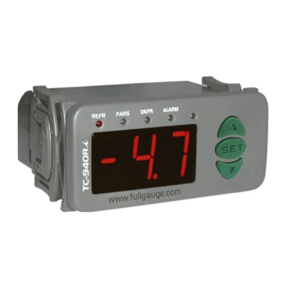
TC-940Ri plus
The
is a temperature controller that manage cycles of defrost, start and finish, when
only necessary, based in evaporator temperature, and they have one output for alarm or shutdown
lamps. They have function to wait residual refrigerant fluid returns in defrost. Thus, it is possible to save
energy and increase the efficiency of the system.
TC-940Ri plus
The
have one digital input for extern synchronize defrost. This same input can
change setpoint to nigthtime mode. This digital input can generate a visual and audible alarm too, to
indicate open door, for exemple.
TC-940Ri plus
The
have a digital filter that simulates an increase response time of sensor S1 to
avoid the compressor action in fast changes of temperature.
They have one serial port to comunicate whith Sitrad .
2. APPLICATION
• Counters
• Refrigerated balcony
3. TECHNICAL SPECIFICATIONS
- Power supply:
12 dc
V
- Control temperature:
-50 to 75° C / -58 to 167°F
- Resolution:
0.1°C from -10 to 75°C and 1°C outside this range / 1°F
- Operating temperature:
0 to 50°C 32 to 122°F
/
- Operating humidity:
10 to 90% RH (without condensation)
- Dimensions:
71 x 28 x 71mm
- Load current (outputs):
COMP: 16(8)A/ 250Vac 1HP (compressor, solenoid valve or contactor)
FANS: 5(3)A/ 250Vac 1/8HP (evaporator fans)
DEFR: 5(3)A/ 250Vac (defrost - resistance or hot gas)
ALRM: 3A/ 250Vac resistive load (external alarm)
4. CONFIGURATIONS
4.1 - Setting the control temperature (SETPOINT)
Press
SET
for two seconds, until the message
temperature will be displayed. Use the keys
save.
If the operating mode of the digital input is configured for nighttime setpoint (F31=3), the message
will be displayed after the message
to allow setting the daytime setpoint. Use the keys
to change the value and then press
SET
nighttime setpoint, use the same procedure above to adjust it and leave the setup mode.
4.2 - Parameters table
Fun
Description
Access code: 123 (one hundred and twenty-three)
Control differential (hysteresis)
Offset indication for ambient sensor
Indication offset of the evaporator temperature (offset)
Minimum setpoint allowed to the end user
Maximum setpoint allowed to the end user
Defrost type (0 = resistance; 1 = hot gas)
Initial defrost condition (0 = time; 1 = temperature)
Period between defrost (if F08 = 0)
Maximum time in refrigeration (for security, if F08 = 1)
Temperature in the evaporator for defrost start (if F08 = 1)
Time of pre-defrost (if F08 = 1)
Defrost when the instrument is powered on (0 - no; 1 - yes)
Evaporator temperature (S2) for end defrost
Maximum defrost duration (for security)
Fan turned on during defrost (0 - no; 1 - yes)
Delay to do the first defrost (if F07 = 0)
Locked temperature indication (S1) during defrost (0 - no; 1 - yes)
Draining time (dripping of defrost water)
Evaporator temperature (S2) for fan return after draining
Maximum time for fan return after draining (fan-delay)
Fan on with compressor off (0 - no; 1 - yes)
Fan stop for high temperature in evaporator
Hysteresis for fan return (after stoping for high temperature
in evaporator)
Low temperature alarm (S1)
Alarm hysteresis of low temperature
High temperature alarm (S1)
Alarm hysteresis of high temperature
Inhibition time of alarm when the instrument is powered on
Inhibition time of alarm after draining
Digital input operating mode
Time for inhibiting the open door alarm
Time for collecting the defrost gas
Delay when the instrumet is powered on
Minimum time of compressor turned on
Minimum time of compressor turned off
Compressor status with detached ambient sensor
(0 = off; 1 = on)
Intensity of the digital filter applied to ambient sensor (S1)
Network equipment address RS - 485
TC-940Ri plus
DIGITAL CONTROLLER FOR
REFRIGERATION AND DEFROST
WITH ALARM OUTPUT
Ver.01
®
appears, and then release. The current working
and
to change the value and then press
to save. Then
will be displayed to allow setting the
CELSIUS
FAHRENHEIT
Min Max Unit Standard Min Max Unit Standard
-99
999
-
-
-99
999
0.1
20.0
°C
1.5
1
36
-20
20.0
°C
0.0
-36
36
-20
20.0
°C
0.0
-36
36
-50
75.0
°C
-50
-58
167
-50
75.0
°C
75.0
-58
167
0
1
-
0
0
1
0
1
-
0
0
1
1
999
min.
240
1
999
1
240
hours
24
1
240
-50
75.0
°C
-5.0
-58
167
0
90
min.
10
0
90
0
1
-
0
0
1
-50
75.0
°C
40.0
-58
167
0
90
min.
45
0
90
0
1
-
0
0
1
0
999
min.
0
0
999
0
1
-
0
0
1
0
30
min.
10
0
30
-50
75.0
°C
0.0
-58
167
0
30
min.
1
0
30
0
1
-
1
0
1
-50
75.0
°C
75.0
-58
167
0.1
20.0
°C
2.0
1
36
-50
75.0
°C
-50
-58
167
0.1
20.0
ºC
1.0
1
36
-50
75.0
°C
75.0
-58
167
0.1
20.0
°C
1.0
1
36
0
999
min.
0
0
999
0
999
min.
0
0
999
0
3
-
0
0
3
0
99
min.
0
0
99
0
90
min.
0
0
90
0
999
min.
0
0
999
0
999
sec.
0
0
999
0
999
s
ec.
0
0
999
0
1
-
1
0
1
0
9
-
0
0
9
0
247
-
1
0
247
4.3 - Parameters description
F01 - Access code (123)
It is necessary to change the configuration parameters. To visualize the adjusted parameters, it is not
necessary to insert this access code.
F02 - Control differential (hysteresis)
It is the difference of temperature (hysteresis) between ON and OFF the refrigeration.
Example:
You need to control temperature in 4.0 ºC with differential of 1.0 ºC.
So, the refrigeration is turned off in 4.0 ºC and will be turned on in 5.0 ºC (4.0 +1.0).
F03 -
Indication offset of the
It allows to compensate eventual shuting lines on reading of ambient temperature (S1), proceeding of
sensor exchange or cable length alteration.
F04 - Indication offset of the evaporator temperature
It allows to compensate eventual shuting lines on reading of ambient temperature (S2), proceeding of
sensor exchange or cable length alteration.
F05 - Minimum setpoint allowed to the end user
F06 - Maximum setpoint allowed to the end user
It is to prevent that incorrect high or low temperatures be regulated.
F07 - Defrost type
"0" = Electrical defrost (resistances),where is kept on only the defrost output.
"1" = Hot gas defrost, where defrost and compressor outputs are kept on.
F08 - Initial defrost condition
It defines if the defrost start will be for temperature or time. Is this function has the value "1", when the
evaporator temperature reaches the configured value in "F11" the instrument starts to count the pre-
defrost time and, after, will do the defrost.
SET
to
F09 - Period between defrosts (if F08 = 0)
It determines the time between two consecutives defrost cycles, and starts to be counted from the last
or
defrost.Attention, the defrost only will start if the temperture in S2 (evaporator sensor) is lower than F14.
F10 - Maximum time in refrigeration (for security, if F08 = 1)
It acts as security time (if F08 = 1) and evaporator temperature will not reach the configured value in
"F11". This function determines the maximum time that controller will stay without defrost.
F11 - Temperature in the evaporator for defrost start (if F08 = 1)
When evaporator temperature reaches the configured value in this function the controller will start to
count the pre-defrost period (F12).
-
-
°F
3
F12 - Time of pre-defrost (if F08=1)
°F
0
At the moment that the temperature in evaporator decreases and reaches the configured value in "F11",
°F
0
start to be counted the pre-defrost time. During the pre-defrost stage, if the temperature is kept low the
°F
-58
defrost starts, else if the temperature increase at least 1 ºC in relation to configured value, the system
returns to refrigeration stage.
°F
167
-
0
F13 - Defrost when the instrument is powered on
-
0
It possibilities the defrost at the moment that the controller is turned on, for example, in return of electrical
min.
240
energy (in case of energy lacks).
hours
24
°F
23
F14 - Evaporator temperature (S2) for end defrost
min.
10
If evaporator temperature (sensor S2) reaches the adjusted value, the end defrost will happen for
-
0
temperature. With this , the defrost process is optimized.
°F
104
F15 - Maximum defrost duration
min.
45
This function serves to adjust the maximum value of time to defrost. If in this period the evaporator
-
0
temperature will not reach the configured value in F14 a point will be blinking on inferior down right side of
-
0
display indicating that the end defrost ocurred for time and not for temperature.
-
0
This can happen when the adjusted temperature is very high, the limit time will be not enough, the S2
sensor is detached or not in contact with the evaporator.
min.
10
°F
32
F16 - Fan turned on during defrost
min.
1
It possibilities the fan functioning during defrost.
-
1
Example: Natural defrost or by resistances installed outside the evaporator.
°F
167
F17 - Delay to do first defrost (if F08=0
°F
4
This function defines an extra time that the instrument will keep in refrigeration before do the first defrost,
°F
-58
to prevent that lot of counters enter in defrost at the same time. This time only appears before the first
ºF
2
defrost, when F08 = 0 (initial defrost for time).
°F
167
°F
2
F18 - Locked temperature indication (S1) during defrost
min.
0
This function prevents that ambient temperature elevation be visualized. During defrost the last
measured temperature in refrigeration cycle will be locked on display. The indication will be released
min.
0
when this temperature will be reached again or 15 minutes after the begin of next refrigeration cycle.
-
0
min.
0
F19 - Draining time (dripping of defrost water)
min.
0
Necessary time for dripping, it means, to drain the last water drops of the evaporator. All the outputs
min.
0
keep turned off. If you do not need this stage, adjust this time for "zero".
sec.
0
sec.
0
F20 - Evaporator temperature (S2) for fan return after draining(fan-delay)
After the draining, the fan-delay cycle starts. The refrigeration (COMP) output is turned on, because the
-
1
evaporator temperature is high, but the fan only is turned on after evaporator temperature decreases the
adjusted value. This process is necessary to remove the heat that exists in the evaporator because the
-
0
defrost, preventing to pass it to the ambient.
-
1
ambient
temperature
)
Advertisement
Table of Contents

Subscribe to Our Youtube Channel
Related Manuals for Full Gauge Controls TC-940Ri plus


Summary of Contents for Full Gauge Controls TC-940Ri plus
- Page 1 TC-940Ri plus DIGITAL CONTROLLER FOR REFRIGERATION AND DEFROST WITH ALARM OUTPUT Ver.01 1. DESCRIPTION 4.3 - Parameters description TC-940Ri plus is a temperature controller that manage cycles of defrost, start and finish, when only necessary, based in evaporator temperature, and they have one output for alarm or shutdown F01 - Access code (123) lamps.
- Page 2 F21 - Maximum time for fan return after draining (fan-delay) 4.3.1 - Unit selection (ºC/ºF) For security, if the evaporator temperature does not reach the adjusted value in F20 or the S2 sensor is To determine the unit that the instrument will work, access the function “F01” with the access cod 231 and detached, the fan-delay will happen after passed the adjusted time in this function.
- Page 3 RS-485 Serial Interface Brown - A Brown - A 72 mm Device used to establish the Red - B Red - B connection Full Gauge Controls’ ® instruments with the Sitrad Serial Serial Distribution Box communication communication RS-485 Used to connect more than one instrument to the Interface.
Need help?
Do you have a question about the TC-940Ri plus and is the answer not in the manual?
Questions and answers