Advertisement
Quick Links
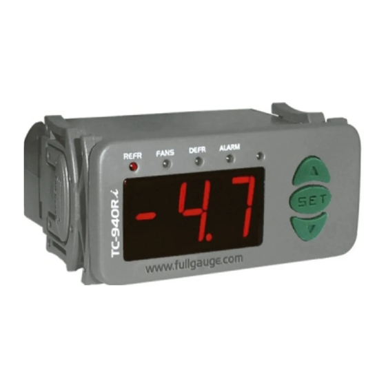
1. DESCRIPTION
O TC-940Ri is a digital controller of temperature that manages defrost cycles and evaporator fans.
This instrument also has an output for alarm.
An innovative feature of TC-940Ri is the possibility that the controller offers initiating a defrost cycle
evaporator temperature, detecting the moment that the system needs to do defrost. Thus, it is possible
to save energy and increase the efficiency of the system.
Product in agreement with CE (European Community) and UL Inc. (USA and Canada).
2. APPLICATION
• Refrigeration counters
• Refrigerated balcony
3.
TECHNICAL SPECIFICATIONS
- Power supply:TC-940Ri - 115/230 Vac ±10% (50/60 Hz)
TC-940RiL - 12/24 Vac/dc
- Control temperature: -50 to 75° C
/ -58 to 167°F
- Resolution: 0.1°C from -10 to 75°C and 1°C outside this range
- Operating temperature: 0 to 50°C / 32 to 122°F
- Operating humidity: 10 to 90% RH (without condensation)
- Dimensions: 71 x 28 x 71mm
- Load current (outputs):
REFR: 5(3)A / 250Vac 1/8HP (compressor, solenoid valve or contactor)
FANS: 5(3)A / 250Vac 1/8HP (evaporator fans)
DEFR: 5(3)A / 250Vac (defrost - resistance or hot gas)
ALRM: 3A / 250Vac resistive load (external alarm)
CLASSIFICATION ACCORDING TO IEC60730-2-9 STANDARD:
- Temperature limit of the installation surface: 50°C / 122°F
- Type of construction: Built-in electronic controller
- Automatic action: Type 1
- Control of pollution: Level 2
- Impulse voltage: 1,5kV
- Temperature for the test of sphere pressure: 75°C and 125°C
- Insulation: Class II
4. CONFIGURATIONS
4.1 - Control temperature adjust (SETPOINT)
Press
for 2 seconds until appears
SET
temperature will appear. Use the keys
and
4.2 - Parameters table
Fun
Description
F01
Access code: 123 (one hundred and twenty-three)
F02
Control differential (hysteresis)
F03
Offset indication for ambient sensor
F04
Minimum setpoint allowed to the end user
F05
Maximum setpoint allowed to the end user
F06
Defrost type (0 = resistance; 1 = hot gas)
F07
Initial defrost condition (0 = time; 1 = temperature)
F08
Period between defrost (if F07 = 0)
F09
Maximum time in refrigeration (for security, if F07 = 1)
F10
Temperature in the evaporator for defrost start (if F07 = 1)
F11
Time of pre-defrost (if F07 = 1)
F12
Defrost when the instrument is powered on (0 - no; 1 - yes)
F13
Evaporator temperature (S2) to finish defrost cycle
F14
Maximum defrost duration (for security)
F15
Fan turned on during defrost (0 - no; 1 - yes)
F16
Delay to do the first defrost (if F07 = 0)
F17
Temperature indication (S1) locked during defrost
(0 - no; 1 - yes)
F18
Draining time (dripping of defrost water)
F19
Evaporator temperature (S2) for fan return after
draining
F20
Maximum time for fan return after draining
(fan-delay)
F21
Fan on with compressor off
(refrigeration)
F22
(0 - no; 1 - yes)Fan stop for high temperature in evaporator
F23
Differential for fan return (after stoping for high temperature
in evaporator)
F24
Low temperature alarm (S1)
F25
Alarm differential of low temperature
F26
High temperature alarm (S1)
F27
Alarm differential of high temperature
F28
Inhibition time of alarm when the instrument is powered on
F29
Inhibition time of alarm after draining
F30
Delay when the instrumet is powered on
F31
Minimum time of compressor turned on
F32
Minimum time of compressor turned off
F33
Compressor status with detached ambient sensor
(0 = off; 1 = on)
TC-940Ri
DIGITAL CONTROLLER FOR
REFRIGERATION AND DEFROST
WITH ALARM OUTPUT
Ver.04
/ 1°F
/ 167°F and 257°F
, and release it after that. The adjusted operation
to change the value and then press
to record it.
SET
CELSIUS
FAHRENHEIT
Min Max Unit
Standard Min Max Unit
-99
999
-
-
-99
999
0.1
20.0
°C
1.5
1
36
°F
-20
20.0
°C
0.0
-36
36
°F
-50
75.0
°C
-50
-58
167
°F
-50
75.0
°C
75.0
-58
167
°F
0
1
-
0
0
1
0
1
-
0
0
1
1
999
min.
240
1
999
min.
1
240
hour
24
1
240
hour
-50
75.0
°C
-5.0
-58
167
°F
0
90
min.
10
0
90
min.
0
1
-
0
0
1
-50
75.0
°C
40.0
-58
167
°F
0
90
min.
45
0
90
min.
0
1
-
0
0
1
0
999
min.
0
0
999
0
1
-
0
0
1
0
30
min.
10
0
30
min.
-50
75.0
°C
0.0
-58
167
°F
0
3
min.
1
0
30
min.
0
1
-
1
0
1
-50
75.0
°C
75.0
-58
167
°F
0.1
20.0
°C
2.0
1
36
°F
-50
75.0
°C
-50
-58
167
°F
0.1
20.0
ºC
1.0
1
36
ºF
-50
75.0
°C
75.0
-58
167
°F
0.1
20.0
°C
1.0
1
36
°F
0
999
min.
0
0
999
min.
0
999
min.
0
0
999
min.
0
999
min.
0
0
999
min.
0
999
sec.
0
0
999
sec.
0
999
sec.
0
0
999
sec.
0
1
-
1
0
1
4.3 - Parameters description
F01 - Access code (123)
It is necessary to change the configuration parameters. To visualize the adjusted parameters, it is not
necessary to insert this access code.
F02 - Control differential (hysteresis)
It is the difference of temperature (hysteresis) between ON and OFF the refrigeration.
Example: You need to control temperature in 4.0 ºC with differential of 1.0 ºC.
So, the refrigeration is turned off in 4.0 ºC and will be turned on in 5.0 ºC (4.0 +1.0).
F03 - Offset indication for ambient sensor
It allows to compensate eventual shuting lines on reading of ambient temperature (S1), proceeding of
sensor exchange or cable length alteration.
F04 - Minimum setpoint allowed to the end user
F05 - Maximum setpoint allowed to the end user
It is to prevent that incorrect high or low temperatures be regulated.
F06 - Defrost type
"0" = Electrical defrost (resistances),where is kept on only the defrost output.
"1" = Hot gas defrost, where defrost and compressor outputs are kept on.
F07- Initial defrost condition
It defines if the defrost start will be for temperature or time. Is this function has the value "1", when the
evaporator temperature reaches the configured value in "F10" the instrument starts to count the pre-
defrost time and, after, will do the defrost.
F08 - Period between defrosts (if F07 = 0)
It determines the time between two consecutives defrost cycles, and starts to be counted from the last
defrost. Attention, the defrost only will start if the temperture in S2 (evaporator sensor) is lower than F13.
F09 - Maximum time in refrigeration (for security, if F07 = 1)
It acts as security time if (F07 = 1) and evaporator temperature will not reach the configured value in
"F10". This function determines the maximum time that controller will stay without defrost.
F10 - Temperature in the evaporator for defrost start (if F07 = 1)
When evaporator temperature reaches the configured value in this function the controller will start to
count the pre-defrost period (F11).
F11 - Time of pre-defrost (se F07=1)
At the moment that the temperature in evaporator decreases and reaches the configured value in "F10",
start to be counted the pre-defrost time. During the pre-defrost stage, if the temperature is kept low the
defrost starts, else if the temperature increase at least 1 ºC in relation to configured value, the system
returns to refrigeration stage.
F12 - Defrost when the instrument is powered on
Standard
It possibilities the defrost at the moment that the controller is turned on, for example, in return of electrical
-
-
energy (in case of energy lacks).
3
F13 - Evaporator temperature (S2) to finish defrost cycle
0
If evaporator temperature (sensor S2) reaches the adjusted value, the end defrost will happen for
-58
temperature. With this , the defrost process is optimized.
167
-
0
F14 - Maximum defrost duration
-
0
This function serves to adjust the maximum value of time to defrost. If in this period the evaporator
240
temperature will not reach the configured value in F13 a point will be blinking on inferior down right side of
display indicating that the end defrost ocurred for time and not for temperature.
24
This can happen when the adjusted temperature is very high, the limit time will be not enough, the S2
23
sensor is detached or not in contact with the evaporator.
10
-
0
F15 - Fan turned on during defrost
104
It possibilities the fan functioning during defrost.
45
-
0
F16 - Delay to do first defrost (if F07=0)
-
0
This function defines an extra time that the instrument will keep in refrigeration before do the first defrost,
-
0
to prevent that lot of counters enter in defrost at the same time. This time only appears before the first
defrost, when F07 = 0 (initial defrost for time).
10
32
F17 - Temperature indication (S1) locked during defrost
This function prevents that ambient temperature elevation be visualized. During defrost the last
1
measured temperature in refrigeration cycle will be locked on display. The indication will be released
when this temperature will be reached again or 15 mintes after the ibegin of next refrigeration cycle.
-
1
F18 - Draining time (dripping of defrost water)
167
Necessary time for dripping, it means, to drain the last water drops of the evaporator. All the outputs
4
keep turned off. If you do not need this stage, adjust this time for "zero".
-58
F19 - Evaporator temperature (S2) for fan return after draining(fan-delay)
2
After the draining, the fan-delay cycle starts. The refrigeration (REFR.) output is turned on, because the
167
evaporator temperature is high, but the fan only is turned on after evaporator temperature decreases the
2
adjusted value. This process is necessary to remove the heat that exists in the evaporator because the
0
defrost, preventing to pass it pass it to the ambient.
0
0
0
0
-
1
UL-Underwriters Laboratories
Advertisement

Related Manuals for Full Gauge Controls TC-940Ri


Summary of Contents for Full Gauge Controls TC-940Ri
- Page 1 This instrument also has an output for alarm. It is necessary to change the configuration parameters. To visualize the adjusted parameters, it is not An innovative feature of TC-940Ri is the possibility that the controller offers initiating a defrost cycle necessary to insert this access code.
- Page 2 F20 - Maximum time for fan return after draining (fan-delay) 5.2 - Parameters alteration For security, if the evaporator temperature does not reach the adjusted value in F19 or the S2 sensor is a) Access the function F01 pressing at the same time for 2 seconds until appear detached, the fan-delay will happen after passed the adjusted time in this function.
- Page 3 Power supply Dimension of the clipping for setting of the instrument in panel Loads supply 72 mm TC-940Ri TC-940RiL Install a magnetic contactor when 4 - 5 115V exceeding specified current. 4 - 6 230V IMPORTANT According to the chapters from the IEC60364 standard: 1: Install protectors against over voltage on power supply.
Need help?
Do you have a question about the TC-940Ri and is the answer not in the manual?
Questions and answers