Table of Contents
Advertisement
Quick Links
1 - DESCRIPTION
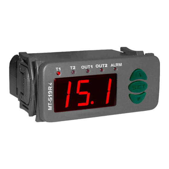
MT519Ri
is a digital controller with two independent thermostats allowing functioning in two
different rooms. In addition, the two thermostat outputs can be configured as cyclic timers. One alarm
output can be linked to one of the thermostats.
2 - APPLICATION
• Boilers
• Ovens
• Heaters
• Freezers
• Chambers
• Hot/cold displays
3 - TECHNICAL SPECIFICATIONS
-
Power supply:
MT-519Ri - 115 or 230 Vac ±10%(50/60 Hz)
MT-519RiL - 12 or 24 Vac/dc
-
Control temperature:
NTC: -50 to 105°C(*) (with resolution of 0.1°C between -10 and 100°C and 1°C
in the rest of the range)
-58 to 221°F(*) (with resolution of 1°F in all range)
OUT1
- Maximum current per output:
and
ALRM
(NF) - 3A/250Vac resistive load
- Dimensions:
71 x 28 x 71 mm
- Operating temperature:
0 to 50 ºC / 32 to 122ºF
- Operating humidity: 10 to 90% RH (without condensation)
(*) This instrument can measure and control up to 200ºC (392°F) temperatures, since used with silicone
cable sensor (eg.: SB59).
4 - CONFIGURATIONS
4.1 - Temperature adjust (SETPOINT)
@
[SET]
- Press
for 2 seconds until until
[F02]
) and the adjusted temperature for the thermostat 1. Use the keys
@
value and, and then press
again.
Set in the same way, the 2nd thermostat (if enabled in
4.2 -
Parameters alteration
[F01]
- To access the function
pressing simultaneously the keys
[Fun]
appearing
, releasing after that. Soon it will appear
>
<
- Use the keys
and
to enter with the access code (123) and, when ready, press
>
<
- Use the keys
and
to access the desired function.
@
- After selecting the function, press
(short touch) to display the configured value for that function.
>
<
- Use the keys
and
to change the value and then press
return to the functions menu.
- To leave the functions menu and return to the normal operation, press
4.3 - Parameters table
Fun
Description
[F01]
Access code: 123 (one hundred and twenty-three)
[F02]
Thermostat 1 o
peration mode
[F03]
Hysteresis of thermostat 1
[F04]
Minimum setpoint allowed to the user (thermostat 1)
[F05]
Maximum setpoint allowed to the user (thermostat 1)
[F06]
Minimum time of
thermostat 1 output
turned off
[F07]
T
hermostat 1 d
elay when the instrument is powered on
[F08]
Cyclic timer operation mode
(thermostat 1)
[F09]
C
yclic timer
- Time off (thermostat 1)
[F10]
C
yclic timer
- Time on (thermostat 1)
[F11]
Temperature sensor offset (thermostat 1)
[F12]
Alarm display mode (thermostat 1)
[F13]
Minimum value of the thermostat 1 alarm
[F14]
Maximum value of the thermostat 1 alarm
[F15]
Activation delay of thermostat 1 alarm
[F16]
Thermostat 2 o
peration mode
[F17]
Hysteresis of thermostat 2
[F18]
Minimum setpoint allowed to the user (thermostat 2)
[F19]
Maximum setpoint allowed to the user (thermostat 2)
[F20]
Minimum time of
thermostat 2 output
turned off
[F21]
T
hermostat 2 d
elay when the instrument is powered on
[F22]
Cyclic timer operation mode
(thermostat 2)
[F23]
C
yclic timer
- Time off (thermostat 2)
[F24]
C
yclic timer
- Time on (thermostat 2)
[F25]
Temperature sensor offset (thermostat 2)
[F26]
Alarm display mode (thermostat 2)
[F27]
Minimum value of the thermostat 2 alarm
[F28]
Maximum value of the thermostat 2 alarm
[F29]
Activation delay of thermostat 2 alarm
[F30]
Alarm output operation mode
[F31]
Alarm output cyclic timer - Time off
[F32]
Alarm output cyclic timer - Time on
[F33]
Preferential display indication
(*) This parameter allows adjustments up to 200ºC (392°F) but to work on these conditions it has to be
used with silicone cable sensor (ex.: SB59).
MT-519Ri
DIGITAL TEMPERATURE
CONTROLLER WITH TWO
INDEPENDENT STAGES
Ver.01
OUT2
: (NA) - 5(3)A/250Vac 1/8HP
[SP1]
appears, then release it.
will appear(if enabled in
>
<
and
to change the
[F16]
).
>
<
and
for 2 seconds until
[F01]
@
and then press
(short touch).
@
@
to record the new value and
@
[---]
until
appear.
CELSIUS
FAHRENHEIT
Min
Max
Unit
Standard
Min Max
-
-99
-99
999
0
999
0
2
-
1
0
2
0.1
5.0
°C
1.0
1
9
(*)
-58
(*)
-50
105
°C
-50
221
(*)
(*)
-58
(*)
-50
105
°C
105
221
0
sec
0
999
0
999
0
sec
0
999
0
999
0
3
-
0
0
3
1
1
999
s/m/h
1
999
s/m/h
1
1
999
s/m/h
1
999
s/m/h
-5.0
5.0
°C
-9
0.0
9
0
4
-
0
0
4
(*)
-58
(*)
-50
105
°C
-50
221
-50
(*)
(*)
-58
(*)
105
°C
105
221
0
0
999
sec
0
999
0
0
2
-
1
2
1.0
0.1
5.0
°C
1
9
-50
-50
(*)
(*)
105
°C
-58
221
(*)
-50
(*)
°C
105
-58
(*)
105
221
0
0
sec
0
999
999
0
0
999
sec
0
999
0
0
0
3
-
3
1
0
999
s/m/h
0
999
s/m/h
0
1
0
999
s/m/h
999
s/m/h
-5.0
5.0
°C
0.0
-9
9
0
4
-
0
0
4
(*)
(*)
-50
-50
-58
105
°C
221
(*)
-50
(*)
°C
-58
(*)
105
105
221
0
sec
0
0
999
999
0
0
4
-
0
4
0
sec
0
999
0
999
0
0
999
sec
0
999
0
0
2
-
0
2
4.4 - Parameters description
[F01]
- Access code (123)
It is necessary to change the configuration parameters. To visualize the adjusted parameters, it is not
necessary to insert this access code.
[F02]
- Thermostat 1 operation mode
Selects the operating mode of thermostat 1:
[OFF]
- Thermostat OFF
configured as s, m or h, output
[Ref]
- Thermostat in refrigeration mode -
the temperature is above the value set in setpoint 1 plus the hysteresis (
the output will be deactivated if the temperature drops below setpoint 1. If
s, m or h, output
Thermostat in heating mode -
temperature is below the value set in setpoint 1 minus the hysteresis (
the output will be deactivated if the temperature rises above setpoint 1. If
s, m or h, output
[F03]
- Hysteresis of thermostat 1
It is the difference of temperature(hysteresis) between turn ON and turn OFF the
[F04]
- Minimum setpoint allowed to the user (thermostat 1)
[F05]
- Maximum setpoint allowed to the user (thermostat 1)
Electronic limits whose purpose is prevent that too high or too low setpoint temperatures are regulated.
[F06]
- Minimum time of thermostat 1 output turned off
It is the minimum time that the
the last stop ant the next start. If
[F07]
- Thermostat 1 delay when the instrument is powered on
A delay that thermostat 1 will wait before activating its control functions. During this time only the
temperature is measured.
[F08]
- Cyclic timer operation mode (thermostat 1)
Allows configuring the cyclic timer associated to output
[OFF]
- Cyclic timer disabled -
to enter.
temperature.
[,S,]
- Cyclic timer activated with time base in seconds
[,M,]
- Cyclic timer activated with time base in minutes
[,H,]
- Cyclic timer activated with time base in hours
For configurations in s, m or h (seconds, minutes or hours) output
long as the temperature of the thermostat needs output
The initial state of
[F09]
- Cyclic timer - Time off (thermostat 1)
[F10]
- Cyclic timer - Time on (thermostat 1)
Unit
Standard
[F09]
Functions
-
base configured in
0
-
1
[F11]
- Temperature sensor offset (thermostat 1)
°F
2
This function allows adjusting any deviation in the reading of sensor 1 caused by an increase (splice) in
°F
-58
the sensor cable or occasional replacement.
°F
(*)
221
[F12]
sec
- Alarm display mode (thermostat 1)
0
Selects how the thermostat 1 checks for the presence of an alarm. The activation of this function only
sec
0
enables the alarm display. If the alarm output must also be enabled, function
-
0
[OFF]
- Alarm off
1
[,1,]
- In-range alarm (
[,2,]
1
- Out-range alarm (
[,3,]
°F
0
- In-range alarm relating to the setpoint (
[,4,]
- Out-range alarm relating to the setpoint (
-
0
°F
-58
[f13]
- Minimum value of the thermostat 1 alarm
(*)
°F
221
[f14]
- Maximum value of the thermostat 1 alarm
sec
0
These are the minimum and maximum values for the alarm to actuate if configured in
-
1
[f15]
- Activation delay of thermostat 1 alarm
2
°F
The time that the alarm of thermostat 1 will remain off even in alarm conditions. This time is counted after
-58
°F
the time configured in
(*)
°F
221
[F16]
0
sec
- Thermostat 2 operation mode
Selects the operating mode of thermostat 2:
0
sec
[OFF]
- Thermostat OFF
0
-
configured as s, m or h, output
1
[Ref]
- Thermostat in refrigeration mode -
1
the temperature is above the value set in setpoint 2 plus the hysteresis (
°F
0
the output will be deactivated if the temperature drops below setpoint 2. If
0
-
s, m or h, output
-58
Thermostat in heating mode -
°F
temperature is below the value set in setpoint 2 minus the hysteresis (
(*)
°F
221
the output will be deactivated if the temperature rises above setpoint 2. If
sec
0
s, m or h, output
0
-
sec
0
sec
0
0
-
- In this mode, temperature sensor 1 can be disconnected. If
OUT1
will operate only as cyclic timer.
In this mode, output
OUT1
will cycle when the thermostat is refrigerating.
In this mode, output
OUT1
will cycle when the thermostat is heating.
OUT1
output will keep turned off, it means, the space of time between
[F08]
is configured as cyclic timer, this time will not be observed.
OUT1
OUT1
Output
will be constantly on or off depending only on the
OUT1
OUT1
is always on
[F10]
OUT1
and
are used when
is configured as cyclic timer, observing the time
[F08]
.
[f13]
[f14]
and
)
[f13]
[f14]
and
)
[sp1] [f13]
-
[sp1] [f13]
[f07]
has elapsed.
- In this mode, temperature sensor 2 can be disconnected. If
OUT2
will operate only as cyclic timer.
In this mode, output
OUT2
will cycle when the thermostat is refrigerating.
In this mode, output
OUT2
will cycle when the thermostat is heating.
[F08]
is
OUT1
will be activated when
[F03
). When activated,
[F08]
is configured as
OUT1
will be activated when the
[F03]
). When activated,
[F08]
is configured as
OUT1
output.
.
OUT1
will keep cycling as
to be activated.
[F30]
must be configured.
[sp1] [f14]
and
+
)
[sp1] [f14]
-
and
+
)
[f12]
.
[F22]
is
OUT2
will be activated when
[F17
). When activated,
[F22]
is configured as
OUT2
will be activated when the
[F17]
). When activated,
[F22]
is configured as
Advertisement
Table of Contents

Subscribe to Our Youtube Channel
Related Manuals for Full Gauge Controls MT-519Ri


Summary of Contents for Full Gauge Controls MT-519Ri
- Page 1 Thermostat in heating mode - In this mode, output will be activated when the Power supply: MT-519Ri - 115 or 230 Vac ±10%(50/60 Hz) [F03] temperature is below the value set in setpoint 1 minus the hysteresis ( ). When activated,...
- Page 2 Loads [f30] supply - Alarm output operation mode Selects how the alarm output is activated Above specified current use [Off] MT-519Ri MT-519RiL - Alarm output off a contactor. 4 - 5 115V [,1,] - The alarm output is activated when there is an alarm for thermostat 1...
- Page 3 PROTECTIVE VINYL This adhesive vinyl (included inside the packing) protects the instruments against water drippings, as in commercial refrigerators, for example. Do the application after finishing the electrical connections. Remove the protective paper and apply the vinyl on the entire superior part of the device, folding the flaps as indicated by the arrows.
Need help?
Do you have a question about the MT-519Ri and is the answer not in the manual?
Questions and answers