
Related Manuals for ABB 2 Series


Summary of Contents for ABB 2 Series
- Page 1 A B B CH A R G I N G S TATI O N Operation and installation manual Terra 360 Series 2 - CE Terra 60 - CE...
- Page 2 Manufacturer and contact data Manufacturer name and address Contact ABB E-mobility, ABB E-mobility in your country can give you support on the EVSE. Heertjeslaan 6 The latest version of this document is available on the website: 2629 JG Delft https://new.abb.com/ev-charging...
-
Page 3: Table Of Contents
Table of contents RFID - Authorization to charge 1. Introduction and general information Payment terminal Disclaimer and warranty conditions Cloud service portal Function and target of this document Description of the touchscreen Language 3.10 EVSE LEDs How to use this document 3.11 Working principles Abbreviations... - Page 4 “Operation and installation manual” - “Terra 360 Series 2 - CE” 6. Installation 9. Maintenance and troubleshooting Installation of the EVSE - Terra 60 Maintenance schedule for the owner 6.1.1 Floor space requirements - Terra 60 Troubleshooting 6.1.2 Prepare the foundation - Terra 60 6.1.3 Remove the base cover - Terra 60 6.1.4 Open the cable glands - Terra 60 6.1.5 Route the cables - Terra 60...
-
Page 5: Introduction And General Information
• User Disclaimer and warranty conditions ABB E-mobility shall not be liable for any damages, losses, costs or expenses resulting from the improper handling of the EVSE, in particular resulting from non compliance with the instructions of this document and other applicable regulations and standards (e.g. -
Page 6: Language
“Operation and installation manual” - “Terra 360 Series 2 - CE” The document is applicable to these EVSE (Including all variants and options): • Terra 360 - Series 2 • Terra 60 - Series 1 NOTE “Terra xx0” is a generic name for the EVSE models to address the main types of the EVSE. Language The original instructions of this document are in English (EN-US). -
Page 7: Terminology
Terminology Description Network operating center Facility of the manufacturer to do a remote check on the correct operation of of ABB EV Infrastructure the EVSE Cabinet Enclosure of the EVSE, including the components on the inside Intermediate unit that provides DC power to the Charge control set. Gets its Power cabinet power from a power distribution board. -
Page 8: Safety
“Operation and installation manual” - “Terra 360 Series 2 - CE” 2. Safety This chapter contains the safety instructions which must obey during installation, commissioning, operation and maintenance of the equipment. Always obey and follow the reading order of instruction exactly as described in this manual to prevent injury or damage to the equipment. -
Page 9: Responsibilities And Qualifications For The Users
Safety • Unprofessional or incorrect installation, installation not complying to standards, or installation not following the installation instructions contained in the product specific manual. • Improper operation (in breach of the technical requirements or specifications or manuals of the product), negligence or repairs carried out by the Owner (or any third party not authorized by the manufacturer). -
Page 10: Risks Related To Improper Use Or Product Defect
“Operation and installation manual” - “Terra 360 Series 2 - CE” 2.2.1 Risks related to improper use or product defect Any improper use of the device is forbidden, even for common other arrangement related to the final scope and function. To avoid any serious consequence on personal safety, please contact the service of the manufacturer in case of need of further warnings concerning the ways in which the equipment must not be used and which could occur. -
Page 11: General Signs And Signal Words
Safety General signs and signal words In the manual and/or in some cases on the equipment, the danger or hazard zones/components are indicated with signs, labels, symbols or icons. Symbol Description General risk With signal word ‘Danger’: If you do not obey the instruction, this can cause injury or death With signal word ‘Warning’: If you do not obey the instruction, this can cause injury With signal word ‘Caution’: If you do not obey the instruction, this can cause damage to the EVSE or to property... -
Page 12: Personal Protective Equipment
“Operation and installation manual” - “Terra 360 Series 2 - CE” Symbol Description Direct current Protective Earth (PE) Sign that means that you must read the manual before you install the EVSE Waste from electrical and electronic equipment NOTE It is possible that not all symbols or signal words are present in this document Personal protective equipment A Personal Protective Equipment (PPE) is clothing or equipment designed to protect/reduce employees from exposure to work place hazards and the risk of injury. -
Page 13: Safety Instructions During Transport
Safety 2.5.1 Safety instructions during transport • Make sure that the hoisting equipment or forklift truck can lift the EVSE safely. • Take into account the mass and the center of gravity of the EVSE. • Obey the applicable safety instructions for the hoisting equipment or for the forklift truck. -
Page 14: Discard The Evse Or Parts Of The Evse
The manufacturer (ABB E-mobility) and its affiliates are not liable for damages and/or losses related to such security breaches, any unauthorized access, interference, intrusion, leakage and/or theft of data or information. - Page 15 Safety For the regulations of individual countries, refer to the national and international certification bodies as follows: Country Standard Description ASTM American Society for Testing and Materials International Organization for Standardization CENELEC European Committee for Electrotechnical Standardization Italy Comitato Elettrotecnico Italiano International International Electrotechnical Commission International...
-
Page 16: Description
“Operation and installation manual” - “Terra 360 Series 2 - CE” 3. Description This chapter contains information about the models, details of the equipment, characteristics and technical data, overall dimensions and equipment identification. A description of the equipment characteristics is provided to identify its main components and specify the technical terminology used in the manual. -
Page 17: Type Plate - Identification Of Equipment
2629 JG Delft, IP54 VDE - XXXXxxxx XX-XXXXX x Class X xxx. xx The Nederlands XX-XXXXX x MADE IN ITALY www.abb.com Ref. Description Address of the manufacturer EVSE rating EVSE identification code Internal product code (for the manufacturer) Production date... -
Page 18: Evse Identification Code
“Operation and installation manual” - “Terra 360 Series 2 - CE” 3.2.1 EVSE identification code In the table is described the structure of the identification code of the EVSE. TDC2L60 CE CJT 5N5 - 5N2 B - 0 EXAMPLE Field Description TTT STPPP •... -
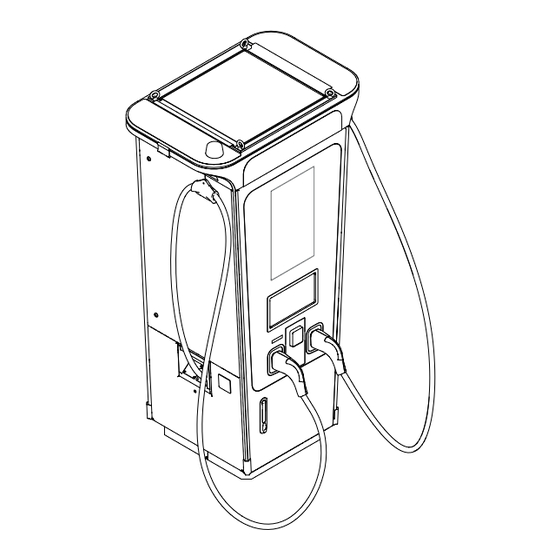
Page 19: Terra 60 Overview
Description Terra 60 Overview 3.3.1 Overview outside - Terra 60 Ref. Part Function Removable base To cover the lower part of EVSE Type plate Identification and technical data label Air inlet. Top left door To filter the air and access the inside of EVSE Cable management system retracts the cables and holds the Cable management system (CMS) cables in position when the EVSE is not in use. -
Page 20: Overview Inside - Terra 60
“Operation and installation manual” - “Terra 360 Series 2 - CE” 3.3.2 Overview inside - Terra 60 Ref. Part Function Power modules To provide power to the EVSE Acoustic baffle To reduce the airflow noise Cable gland plate Plate with openings for power and signal cables PE busbar To connect Protective Earth (PE) cables Main AC switch... -
Page 21: Overview Air Openings And Filters - Terra
Description 3.3.3 Overview air openings and filters - Terra 60 Ref. Part Function To let cooling air in. The airflow makes sure that the parts on Air inlet the inside of the EVSE do not become too hot To let cooling out. The airflow makes sure that the parts on Air outlet the inside of the EVSE do not become too hot Air outlet filter... -
Page 22: Terra 360 Overview
“Operation and installation manual” - “Terra 360 Series 2 - CE” Terra 360 Overview 3.4.1 Overview outside - Terra 360 Ref. Part Function Removable base To cover the lower part of EVSE Bottom left door To access the inside of EVSE Type plate Identification and technical data label Air inlet. -
Page 23: Overview Inside - Terra 360
Description 3.4.2 Overview inside - Terra 360 7 10 1 8 11 2 9 12 3 Ref. Part Function Power modules To provide power to the EVSE Acoustic baffle To reduce the airflow noise Cable gland plate Plate with openings for power and signal cables PE busbar To connect Protective Earth (PE) cables Main AC switch... -
Page 24: Overview Air Openings And Filters - Terra
“Operation and installation manual” - “Terra 360 Series 2 - CE” 3.4.3 Overview air openings and filters - Terra 360 Ref. Part Function To let cooling air in. The airflow makes sure that the parts on Air inlet the inside of the EVSE do not become too hot To let cooling out. -
Page 25: System Overview
The touchscreen guides the user how to use the payment terminal. NOTE To use and adjust the settings of the payment terminal, ABB Payment Web tool is required. Cloud service portal ABB E-mobility provides a set of cloud-based tools to commission, monitor and troubleshoot the EVSE. Please... -
Page 26: Description Of The Touchscreen
“Operation and installation manual” - “Terra 360 Series 2 - CE” Description of the touchscreen Layout of the display: Welcome First select your output. CHAdeMO Ref. Description Field to select the connector type Instruction field Information button Selected language Description of the buttons: Button Name Description... -
Page 27: Evse Leds
Description 3.10 EVSE LEDs The charger is equipped with LED strips that indicates the EVSE status based on the colour. In the table are described the main status: LEDs Description The EVSE is in idle mode and ready for use: The top LEDs of the EVSE are green One charge session starts: The side LEDs of the selected outlet change to blue... -
Page 28: Working Principles
“Operation and installation manual” - “Terra 360 Series 2 - CE” 3.11 Working principles 3.11.1 Block diagram - Terra 60 Par. Description Fused manual switch Auxiliary fuse switch Magnetic circuit breaker** Auxiliary magnetic circuit breaker** Auxiliary residual-current device AC socket residual current device** AC surge-protection device LED strip power supply Auxiliary power supply... -
Page 29: Block Diagram - Terra 360 (Simple Power Distribution)
Description 3.11.2 Block diagram - Terra 360 (simple power distribution) Block diagram of Terra 360 with simple power distribution, allocation power with a resolution of 50% of the rated power. Par. Description Fused manual switch Auxiliary fuse switch Auxiliary residual-current device AC surge-protection device LED strip power supply Auxiliary power supply... -
Page 30: Power Allocation Strategies
“Operation and installation manual” - “Terra 360 Series 2 - CE” 3.12 Power allocation strategies Before the manufacturer starts the commissioning procedure, you must select one of the power allocation strategies. The configuration of the EVSE allows for these power allocation strategies: Power allocation strategy Available for EVSE models Sequential... -
Page 31: Share Mode
4G LTE bands 2 (1900 MHz), 4 (1700/2100MHz), or 12 (700 MHz). NOTE The Charger supports SIM cards provided by ABB only. Any other types of SIM cards are not supported. 3.13.2 Internet via ethernet connection If the cellular connection is not available, ethernet connection must be made to the charger. -
Page 32: Options
“Operation and installation manual” - “Terra 360 Series 2 - CE” 3.14 Options 3.14.1 Fiscal metering system The EVSE can optionally be equipped with a DC energy meter (this option can be installed in the factory or in the field) Ref. -
Page 33: Transport, Handling And Unpacking
Transport, handling and unpacking 4. Transport, handling and unpacking In this section are explained all the transport specification, including handling and unpacking procedures of the EVSE. Chapter recipients: • Owner • Qualified installer Transport of the EVSE - Preliminary operation A transport company delivers the EVSE close to the site. -
Page 34: Hoist The Packaged Evse
“Operation and installation manual” - “Terra 360 Series 2 - CE” • Do a check on the transport sensors: - If the sensor (A) show a red indication a shock was detected. ShockDot ShockDot WARNING WARNING ShockDot ShockDot WARNING WARNING - If the sensors (B) show a tilt that is too high. -
Page 35: Move The Packaged Evse With A Forklift Truck
Transport, handling and unpacking 4.1.2 Move the packaged EVSE with a forklift truck • Move the forks of the forklift truck in the gaps of the pallet. WARNING Risk of pinching or crushing, the EVSE is heavy • Obey the safety instructions that apply to the forklift truck. •... -
Page 36: Unpacking
“Operation and installation manual” - “Terra 360 Series 2 - CE” • Pay attention to the side/forward slopes of the floor Unpacking 4.2.1 Unpacking procedure WARNING Packaging elements (cardboard, cellophane, staples, adhesive tape, straps, etc.) may cause cuts and/or injuries if not handled with care. They should be removed with the proper equipment. NOTE The components of the packaging must be disposed in accordance with the regulations in force in the country of installation. -
Page 37: Components Supplied With The Evse
Transport, handling and unpacking 4.2.2 Components supplied with the EVSE When the EVSE is unpacked, make sure all components supplied with the EVSE are present: Component Description Quantity Keys to open the EVSE doors AC connection lexan cover (placed on the internal rear side) Bolts + spring washers + flat washers to 4 + 4 + 4... -
Page 38: Access To The Internal Parts
“Operation and installation manual” - “Terra 360 Series 2 - CE” 5. Access to the internal parts In this section are illustrated all the acces procedures. Chapter recipients: • Qualified installer Open the doors - Terra 60 HAZARDOUS VOLTAGE Make sure that only qualified persons have access to the door key. NOTE There is one unique door key for each EVSE. -
Page 39: Open The Rear Door - Terra 60
Access to the internal parts 5.1.2 Open the rear door - Terra 60 Rear door (H) Use the door key to unlock the lock (F) and open the upper right door (D). Unscrew the bolts on the 3 internal latches on the inside of the EVSE Use the door key to unlock the lock (K) and open the rear door (H). -
Page 40: Open The Sides Doors - Terra 60
“Operation and installation manual” - “Terra 360 Series 2 - CE” 5.1.3 Open the sides doors - Terra 60 Upper right door (D) Upper left door (D) Turn the 2 latches (F) and open the upper right Turn the 2 latches (O) and open the upper left door (D). -
Page 41: Open The Doors - Terra
Access to the internal parts Open the doors - Terra 360 HAZARDOUS VOLTAGE Make sure that only qualified persons have access to the door key. NOTE There is one unique door key for each EVSE. 5.4.1 Open the front door - Terra 360 Front door (A) Use the door key to unlock the lock (B) and open the front door (A). -
Page 42: Open The Upper Sides Doors - Terra
“Operation and installation manual” - “Terra 360 Series 2 - CE” 5.4.3 Open the upper sides doors - Terra 360 Upper right door (D) Upper left door (D) Open the front door (A) and unlock the internal Open the rear door (H) and unlock the internal latch (E). -
Page 43: Close The Doors - Terra
Access to the internal parts Close the doors - Terra 360 Hazardous voltage Make sure that only qualified persons have access to the door key. NOTE There is one unique door key for each EVSE. In order to close the doors of the EVSE, repeat the operations described in the “Open doors paragraphs” in reverse order. -
Page 44: Installation
“Operation and installation manual” - “Terra 360 Series 2 - CE” 6. Installation In this section are illustrated all the installation procedure. Chapter recipients: • Owner • Qualified installer Installation of the EVSE - Terra 60 6.1.1 Floor space requirements - Terra 60 FRONT SIDE Parameter Description... -
Page 45: Prepare The Foundation - Terra 60
Installation 6.1.2 Prepare the foundation - Terra 60 6.1.2.1 Prepare the prefabricated foundation - Terra 60 • Take the prefabricated foundation (A). NOTE Contact the manufacturer to order the foundation for your EVSE. NOTE Refer to “11.3. Prefabricated foundation - Terra 60”... -
Page 46: Remove The Base Cover - Terra 60
“Operation and installation manual” - “Terra 360 Series 2 - CE” 6.1.3 Remove the base cover - Terra 60 • Take the base and remove the 4 screws (A) • Remove the base covers (B) 6.1.4 Open the cable glands - Terra 60 •... -
Page 47: Install The Base - Terra 60
Installation 6.1.6 Install the base - Terra 60 • Put the base (A) on the foundation (B) and use it as a drilling template • Drill the 6 holes (C) in the foundation • Use the bolts (D) to install the base on the foundation. •... -
Page 48: Install The Evse On The Base - Terra 60
“Operation and installation manual” - “Terra 360 Series 2 - CE” 6.1.9 Install the EVSE on the base - Terra 60 NOTE The EVSE is screwed to the pallet for transportation. • Connect the ropes/chains of the hoisting equipment to the eyebolts installed on the top side of EVSE. - Page 49 Installation • Move the EVSE (A) on top of the base (B). Use a crane or a forklift. • Carefully lower the EVSE on the base. Make sure that cables do not get trapped between the EVSE and the base. •...
-
Page 50: Installation Of The Evse - Terra 360 Series
“Operation and installation manual” - “Terra 360 Series 2 - CE” Installation of the EVSE - Terra 360 Series 2 6.2.1 Floor space requirements - Terra 360 FRONT SIDE Parameter Description Specification [mm] Space to open the left side door Space to open the right side panel Space to open the rear door 1000... -
Page 51: Assembly The Base - Terra
Installation 6.2.2.2 Prepare a cast foundation - Terra 360 • Make the cast foundation according to the specifications NOTE Refer to “11.2. Footprint - Terra 360” for the foundation specifications. • Prepare the site and the conduits • Route the power and signal cables thought the conduits highlighted in blue applying each cable slack of 1000 mm. -
Page 52: Open The Ac Input Cable Inlets - Terra
“Operation and installation manual” - “Terra 360 Series 2 - CE” 6.2.5 Open the AC input cable inlets - Terra 360 B C D • Unscrew the bolts (A) to open the cable inlets. • Open the cable inlets for these cables: L1 input cable (B) L2 input cable (C) L3 input cable (D) -
Page 53: Install The Base - Terra
Installation 6.2.8 Install the base - Terra 360 • Put thee base (A) on the foundation (B) and use it as a drilling template • Drill the 6 holes (C) in the foundation • Use the bolts (D) to install the base on the foundation. •... -
Page 54: Install The Base Covers - Terra
“Operation and installation manual” - “Terra 360 Series 2 - CE” 6.2.10 Install the base covers - Terra 360 • Install the base covers • Screw the 4 fastners 6.2.11 Install the EVSE on the base - Terra 360 NOTE The EVSE is screwed to the pallet for transportation. - Page 55 Installation • Move the EVSE (A) on top of the base (B). Use a crane or a forklift. • Carefully lower the EVSE on the base. Make sure that cables do not get trapped between the EVSE and the base. •...
-
Page 56: Electrical Connection
“Operation and installation manual” - “Terra 360 Series 2 - CE” 7. Electrical connection In this section are listed all the electrical connection procedure. Chapter recipients: • Qualified installer Protective earth (PE) HAZARDOUS VOLTAGE Before carrying out any operation, check that any external switch of voltage sources (downstream to the EVSE) are in OFF position and check for voltage absence on the AC conductors! The EVSE must be earthed via the connection points marked with the protective earth symbol and using a cable with an appropriate conductor cross-section for the maximum ground fault current that the system... -
Page 57: Connect The Pe Wire
Electrical connection 7.1.1 Connect the PE wire • Cut the cables to the correct length and install cable lugs. • Install the Main Protective Earth (PE) cable (A) to the PE busbar (identified by the PE symbol). NOTE The Terra 360 model has an additional PE busbar to connect the big size cable in vertical position. - Page 58 “Operation and installation manual” - “Terra 360 Series 2 - CE” NOTE Operation in IT networks is not allowed. NOTE The neutral (N) connection is not present in all EVSE models (dashed line on the below schematics). HAZARDOUS VOLTAGE The EVSE’s protective earth (PE) connection is mandatory. TN-C TN-C TN-C-S...
-
Page 59: External Ac Input Protections
Electrical connection 7.2.2 External AC input protections General shematic to identify the position of AC protection devices. Parameter Description Medium voltage network Medium voltage breaker Low voltage network Automatic circuit breaker EVSE Residual current Device (RCD) (opt.) 7.2.2.1 Overcurrent protection An external overcurrent protection device shall be installed to protect medium voltage transformer-EVSE line. -
Page 60: Connect The Ac Wires - Terra 60
“Operation and installation manual” - “Terra 360 Series 2 - CE” 7.2.3 Connect the AC wires - Terra 60 • Connect the AC cables to the main switch terminals. Respect the components sequence shown in the figure. • Tighten the fasteners respeting following torque: Cross section (mm Torque (Nm) L1 (Brown) 150... -
Page 61: Ethernet
If an on-site internet connection is available, the charger will be automatically configured to transmit telemetry data to the ABB EVCI Cloud without the need to install any additional devices (the logging functionality is already integrated into the charger by default). ABB’s EVCI cloud platform consists of several solutions for monitoring and management of chargers in real-time. -
Page 62: Tilt Sensor (Optional)
Ask ABB E-mobility B.V. Refer to section About this document. NOTE The shown branch circuit breaker, 24 V DC supply delivered from an UPS and all other components are not within the scope of ABB E-mobility, therefore are not provided in the EVSE. NOTE Refer to “10.1. -
Page 63: Connect The Tilt Sensor
Electrical connection 7.4.1 Connect the tilt sensor • Cut the wires (B) (C) (D) (E) (F) so that it reaches the bottom side of the terminal block X142 (A). The connector is located in the AC section (see the position of the connector in the side illustration). -
Page 64: Operation And Correct Use
“Operation and installation manual” - “Terra 360 Series 2 - CE” 8. Operation and correct use This chapter will give instruction on the correct use of the EVSE. Chapter recipients: • Owner • Qualified installer • User Prepare for commissioning Danger: Hazardous voltage Do not commission the EVSE. -
Page 65: Prepare Before Use
Operation and correct use Prepare before use • Appoint a site operator and an installation engineer, if these are other persons than you. • Make sure that the EVSE is installed according to the instructions in “. Operation and installation manual”. -
Page 66: Stop A Charge Session
“Operation and installation manual” - “Terra 360 Series 2 - CE” 8.3.2 Stop a charge session • On the touchscreen, press the Stop button. NOTE When the battery is full, the charge session stops automatically. Danger: Hazardous voltage The connector is unlocked by the vehicle. •... -
Page 67: Maintenance And Troubleshooting
Maintenance and troubleshooting 9. Maintenance and troubleshooting In this section the user will be istructed on maintenance and cleaning procedures. Preliminary requirements Owner Maintenance schedule for the owner Frequency Task Procedure Do a check for damage: Check for: 3 months - EV charge cables •... -
Page 68: Troubleshooting
“Operation and installation manual” - “Terra 360 Series 2 - CE” Troubleshooting In the table are given all the needed information applicable to find a solution for an issues. NOTE If you cannot find a solution for the problem, please contact your local manufacturer service dept. Problem Possible cause Possible solution... -
Page 69: Technical Data
Technical data 10. Technical data This chapter contains information about the models, details of the equipment, characteristics and technical data, overall dimensions and equipment identification. A description of the equipment characteristics is provided to identify its main components and specify the technical terminology used in the manual. - Page 70 “Operation and installation manual” - “Terra 360 Series 2 - CE” EVSE Terra 60 CCT AC Input Input connection 3 Phases + N + PE Input voltage 400 Vac +/- 10% Input frequency 50 Hz Input Current 125 A Input power 86KVA Power Factor >...
- Page 71 IEC 62196-2, IEC 62196-3 Communication to the EV DIN 70121, ready for ISO 15118 - 2 Plug’n’Charge 1. ABB uses AC cables/connectors from suppliers, who also declare compliance with this standard 10.1.2 Technical data table - Terra 360 EVSE Terra 360 CC...
- Page 72 301908-2 V13.1.1:2020, EN IEC 62311:2020 Additional compliace with standards IEC 62196-2, IEC 62196-3 Communication to the EV DIN 70121, ready for ISO 15118 - 2 Plug’n’Charge 1. ABB uses AC cables/connectors from suppliers, who also declare compliance with this standard...
-
Page 73: Cable Specifications
Technical data 10.2 Cable specifications EVSE Terra 60 Terra 360 AC Input 150 mm 2 x 240 mm AC cable cross section (recommend) (recommend) AC connection type M10 cable lug M12 cable lug AC cable diameter (cable entry plate) 27...35 mm Max. -
Page 74: Charging Interface
“Operation and installation manual” - “Terra 360 Series 2 - CE” 10.4 Charging interface Charging interface Max. Voltage capability [V] Max. current capability [A] CCS2 combo 2 (air cooled) 200 A / 250 A / 1.000V DC 400 A (500 A Boost) DC CHAdeMO (air cooled) 500V DC... -
Page 75: Output Current Vs Output Voltage Curve
Technical data 10.5 Output current Vs output voltage curve Output current in function of output voltage 10.5.1 Output current Vs output voltage - Terra 60 Single session Dual session (per outlet) Output voltage [V] Output current in function of output voltage 10.5.2 Output current (peak) Vs output voltage - Terra 360 Output power in function of output voltage Single session... -
Page 76: Output Power Vs Output Voltage Curve
Output current in function of output voltage “Operation and installation manual” - “Terra 360 Series 2 - CE” 10.6 Output power Vs output voltage curve Output power in function of output voltage 10.6.1 Output power Vs output voltage - Terra 60 Single session Dual session (per outlet) -
Page 77: Height Of User Operable Elements
Technical data 10.7 Height of user operable elements Parameter Description Specification [mm] Ground level Maximum height of the user operable 1218 elements according to ADA Lowest height of the user operable elements according to ADA EVSE highest user operable element 1203 EVSE lowest user operable element EVSE base... -
Page 78: Attachments
“Operation and installation manual” - “Terra 360 Series 2 - CE” 11. Attachments In this section additional tecnical drawing, specification, schematics are given. NOTE If you need further information, please contact your local manufacturer service dept. Refer to section “Manufacturer and contact data” Chapter recipients: •... -
Page 79: Footprint - Terra
Attachments 11.1 Footprint - Terra 60 The drawing (top view) shows all the necessary measurements to: • drill the holes to fasten the EVSE to the floor/basement (in yellow) • prepare the position of the cables in the ground (in blue) FRONT SIDE... - Page 80 “Operation and installation manual” - “Terra 360 Series 2 - CE” 11.2 Footprint - Terra 360 The drawing (top view) shows all the necessary measurements to: • drill the holes to fasten the EVSE to the floor/basement (in yellow) • prepare the position of the cables in the ground (in blue) 612,9 124,5 FRONT SIDE...
-
Page 81: Prefabricated Foundation - Terra
Attachments 11.3 Prefabricated foundation - Terra 60 The drawing shows all the necessary measurements of the prefabricated foundation: NOTE On the top side of the prefabricated foundation an arrow indicates the front side. NOTE Each side has a square hole XxY = 237 x 165 mm to fit the conduits 1 x 160 mm and 1 x 75 mm diameters or different combinations. -
Page 82: Prefabricated Foundation - Terra
“Operation and installation manual” - “Terra 360 Series 2 - CE” 11.4 Prefabricated foundation - Terra 360 The drawing shows all the necessary measurements of the prefabricated foundation: NOTE On the top side of the prefabricated foundation an arrow indicates the front side. NOTE Each side has a square hole XxY = 237 x 165 mm to fit the conduits 1 x 160 mm and 1 x 75 mm diameters or different combinations. -
Page 83: Messrichtigkeitshinweise Gemäß Baumusterprüfbescheinigung
Attachments 11.5 Messrichtigkeitshinweise gemäß Baumusterprüfbescheinigung Auflagen für den Betreiber der Ladeeinrichtung, die dieser als notwendige Voraussetzung für einen bestimmungsgemäßen Betrieb der Ladeeinrichtung erfüllen muss. Der Betreiber der Ladeeinrichtung ist im Sinne § 31 des Mess- und Eichgesetzes der Verwender des Messgerätes. Die Ladeeinrichtung gilt nur dann als eichrechtlich bestimmungsgemäß... - Page 84 “Operation and installation manual” - “Terra 360 Series 2 - CE” Für den Verwender der Messwerte entstehen aus dieser Regelung konkret folgende Pflichten einer eichrechtkonformen Messwertverwendung: Der Vertrag zwischen EMSP und Kunden muss unmissverständlich regeln, dass ausschließlich die Lieferung elektrischer Energie und nicht die Ladeservice-Dauer Gegenstand des Vertrages ist. 2.
- Page 85 — https://new.abb.com/ev-charging...
Need help?
Do you have a question about the 2 Series and is the answer not in the manual?
Questions and answers