ABB ACQ580-01 Quick Installation And Start-Up Manual
Hide thumbs
Also See for ACQ580-01:
- Quick installation and start-up manual (218 pages) ,
- Installation supplement manual (264 pages) ,
- Installation manual (238 pages)
Table of Contents
Advertisement
Quick Links
—
DRIVES FOR WATER
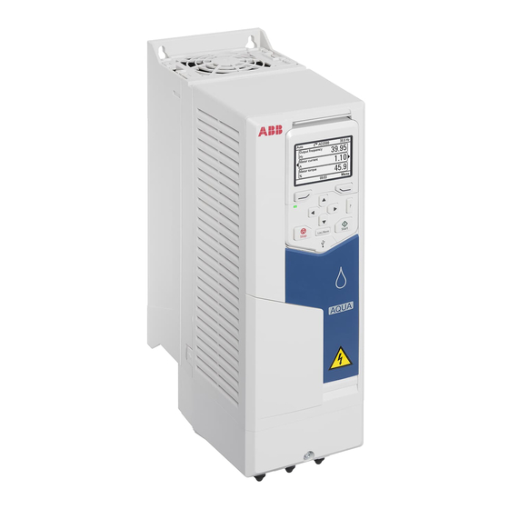
ACQ580-01 drives
Quick installation and start-up guide
This guide is applicable to the global product types. There is a separate guide for the North American product types.
Documentation in other languages
Safety instructions
WARNING! Obey these instructions. If you ignore them, injury or death, or damage to the equipment can occur. If
you are not a qualified electrical professional, do not do electrical installation or maintenance work.
•
Do not do work on the drive, motor cable, motor, or control cables when the drive is connected to the input power.
Before you start the work, isolate the drive from all dangerous voltage sources and make sure that it is safe to start the
work. Always wait for 5 minutes after disconnecting the input power to let the intermediate circuit capacitors
discharge.
•
Do not do work on the drive when a rotating permanent magnet motor is connected to it. A rotating permanent
magnet motor energizes the drive, including its input and output terminals.
•
Frames R1...R2, IP21
(UL Type 1): Do not lift the
drive by holding it from the
cover. The cover can come
loose and cause the drive to
fall.
•
Frames R5...R9: Do not tilt the
drive. The drive is heavy and
has a high center of gravity. It
can topple accidentally.
•
Frames R5...R9: Lift the drive
with a lifting device. Use the
lifting eyes of the drive.
1. Unpack the delivery
Keep the drive in its package until you are ready to install it. After unpacking, protect the drive from dust, debris and
moisture. Make sure that these items are included:
•
cable box (frames R1...R2 and R5...R9, IP21 [UL Type 1])
•
drive
•
mounting template
•
control panel
•
quick installation and start-up guide
•
multilingual residual voltage warning stickers
•
hardware and firmware manuals, if ordered
•
options in separate packages, if ordered.
Make sure that there are no signs of damage to the items.
2. Reform the capacitors
If the drive has not been powered up for a year or more, you must reform the DC link capacitors. Refer to
reforming instructions (3BFE64059629 [English])
Ecodesign information
(EU 2019/1781 and SI 2021 No. 745)
R1...R2
R5...R9
or contact ABB technical support.
About this document
3AXD50000758692 Rev C EN
2023-09-12
© 2023 ABB. All rights reserved.
Original instructions.
R5...R9
Capacitor
1
Advertisement
Table of Contents

Related Manuals for ABB ACQ580-01


Summary of Contents for ABB ACQ580-01
- Page 1 (EU 2019/1781 and SI 2021 No. 745) About this document 3AXD50000758692 Rev C EN 2023-09-12 © 2023 ABB. All rights reserved. Original instructions. Safety instructions WARNING! Obey these instructions. If you ignore them, injury or death, or damage to the equipment can occur. If you are not a qualified electrical professional, do not do electrical installation or maintenance work.
-
Page 2: Install The Drive On The Wall
Select the power cables. Obey the local regulations. • Input power cable: ABB recommends to use symmetrical shielded cable (VFD cable) for the best EMC performance. • Motor cable: Use symmetrical shielded cable (VFD cable) for the best EMC performance. Symmetrical shielded cable also reduces bearing currents, wear, and stress on motor insulation. - Page 3 R1…R4 R6…R9 × 2 × 2 × 2 × 2 × 4 Frames R1…R4: Put the drive on the wall and tighten the screws Frame R5, IP21 (UL Type 1): Install the cable box M5×3...
-
Page 4: Remove The Cover(S)
Frames R5…R9: Put the drive on the wall and tighten the screws R6…R9 6. Remove the cover(s) R1…R4, IP21 (UL Type 1) R5, IP21 (UL Type 1) R5, IP21 (UL Type 1) R6…R9, IP21 (UL Type 1) R1…R9, IP55 (UL Type 12) 7. - Page 5 1) A residual current device must be installed in the supply system. 2) ABB does not guarantee the EMC category or the operation of the ground leakage detector built inside the drive. 10. Measure the insulation resistance of the power cables and the motor Measure the insulation resistance of the input cable before you connect it to the drive.
-
Page 6: Connection Procedure
360° grounding of the cable shield is required for the motor cable and brake resistor cable (if used). It is also recommended for the input power cable. If necessary, install an external filter (du/dt, common mode, or sine filter). Filters are available from ABB. ... - Page 7 • Frames R8…R9: If you use only one conductor, ABB recommends that you put it under the upper pressure plate. If you use parallel power cables, put the first conductor under the lower pressure plate and the second under the upper pressure plate.
- Page 8 Frames R1…R2, R4, R6…R9: Install the grounding shelf. In frames R6…R9, this is the grounding shelf for the control cables. R1…R2 R6…R9 Frame R5: Install the cable box plate (a) and shroud (b). Attach the cables outside the drive mechanically. Ground the motor cable shield at the motor end.
-
Page 9: Connect The Control Cables
12. Connect the control cables Make the connections according to the application. Keep the signal wire pairs twisted as near to the terminals as possible to prevent inductive coupling. Cut a hole into the rubber grommet and slide the grommet onto the cable. Ground the outer shield of the cable 360°... - Page 10 Control cable installation examples This section shows examples for routing the control cables in frames R4 and R6…R9. Frames R1…R3 and R5 are similar to frame R4. R6…R9 Embedded fieldbus connection You can connect the drive to a serial communication link with a fieldbus adapter module or the embedded fieldbus interface.
- Page 11 13. Install optional modules, if included in the delivery 14. Install the cover(s) The cover installation procedure is the opposite of the removal procedure. Refer to Remove the cover(s). In frames R6…R9, install the side plates shown in Connection procedure before you install the cover.
-
Page 12: Fieldbus Communication
3381 Output phase loss All three phases are not connected to the motor. 5090 STO hardware failure STO hardware diagnostics has detected hardware failure. Contact ABB. A5A0 5091 Safe torque off The Safe torque off (STO) function is active. A7CE... - Page 13 3) The drive is suitable for use on a circuit capable of delivering not more than 100000 symmetrical amperes (rms) at 480 V maximum when protected by the fuses given in this table. 4) Refer to Alternate Fuses, MMPs and Circuit Breakers for ABB Drives (3AXD50000645015 [English]) for additional UL fuses and circuit breakers that can be used as branch circuit protection.
- Page 14 Terminal data for the power cables Frame T1/U, T2/V, T3/W, L1, L2, L3, R-, R+/UDC+ size Min. wire size Max. wire size Tightening torque Max. wire size Tightening torque (solid/stranded) (solid/stranded) (solid/stranded) N·m lbf·ft N·m lbf·ft 0.2/0.2 16/16 0.5/0.5 16/16 16/16 0.5/0.5 35/35...
-
Page 15: Ambient Conditions
TT, and IT (ungrounded or high-resistance symmetrically grounded). For the installation requirements for corner-grounded systems at this altitude, contact your local ABB representative. Surrounding air temperature Operation: -15 … +50 °C (5 … 122 °F). No frost permitted. At temperatures over 40 °C (104 °F), the rated output current must be derated by 1% for each added 1 °C (1.8 °F). -
Page 16: Related Documents
The product(s) referred in this Declaration of conformity fulfil(s) the relevant provisions of other European Union Directives which are notified in Authorized to compile the technical file: ABB Limited, Daresbury Park, Cheshire, United Kingdom, WA4 4BT. Single EU Declaration of conformity 3AXD10000497692.
Need help?
Do you have a question about the ACQ580-01 and is the answer not in the manual?
Questions and answers