Table of Contents
Advertisement
Quick Links
Operating & Installation Instructions
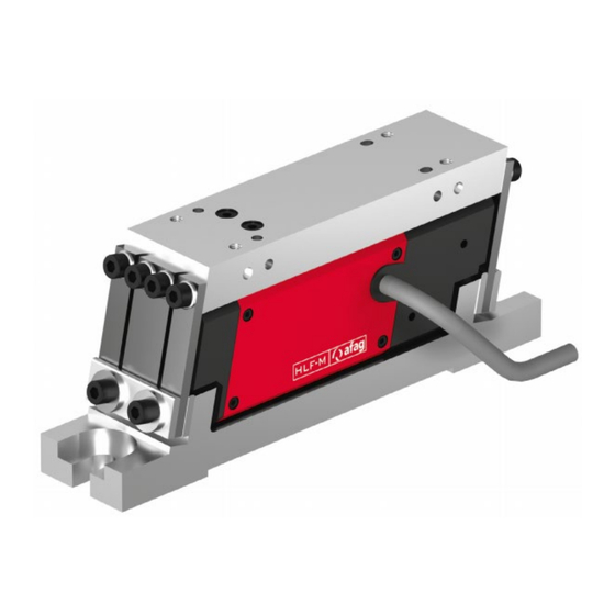
HLF07-M / 12-M / 25-M / 50-M
Translation of the Original Operating & Installation Instructions EN
Linear feeder HLF07-M (230 V/50 Hz)
Linear feeder HLF07-M (115 V/60 Hz)
Linear feeder HLF12-M (230 V/50 Hz)
Linear feeder HLF12-M (115 V/60 Hz)
Linear feeder HLF25-M (230 V/50 Hz)
Linear feeder HLF25-M (115 V/60 Hz)
Linear feeder HLF50-M (230 V/50 Hz)
Linear feeder HLF50-M (115 V/60 Hz)
Operating & Installation Instructions
Linear Feeder
Order no .: 50260370
Order no .: 50270718
Order no.: 50259924
Order no.: 50270770
Order no .: 50259276
Order no .: 50270897
Order no.: 50421880
Order no.: 50431259
EN
HLF07-M/12-M/25-M/50-M
Date 23.08.2023
Version 6.0
1–44
Advertisement
Table of Contents

Subscribe to Our Youtube Channel
Related Manuals for Afag HLF07-M


Summary of Contents for Afag HLF07-M
- Page 1 Operating & Installation Instructions Linear Feeder HLF07-M / 12-M / 25-M / 50-M Translation of the Original Operating & Installation Instructions EN Linear feeder HLF07-M (230 V/50 Hz) Order no .: 50260370 Linear feeder HLF07-M (115 V/60 Hz) Order no .: 50270718...
- Page 2 Your Afag team © Subject to modifications The linear feeders have been designed by Afag Automation AG according to the state of the art. Due to the constant technical development and improvement of our products, we reserve the right to make technical changes at any time.
-
Page 3: Table Of Contents
Transport ....................19 Packaging ....................19 Storage ....................... 19 Design and description ..................20 Design HLF-M linear feeder ............... 20 Description of the HLF-M linear feeder ............20 Operating & Installation Instructions HLF07-M/12-M/25-M/50-M Date 23.08.2023 Version 6.0 3–44 ... - Page 4 9.4.1 Spare parts ................... 38 9.4.2 Wear parts .................... 38 Decommissioning, disassembly, disposal ............39 10.1 Safety instructions ..................39 10.2 Decommissioning ..................39 10.3 Disposal ...................... 39 4 – 44 Operating & Installation Instructions EN HLF07-M/12-M/25-M/50-M Date 23.08.2023 Version 6.0 ...
-
Page 5: General
NOTICE This safety note points out a potentially dangerous situation which, if not avoided, can cause substantial damage to property and the environment. Operating & Installation Instructions HLF07-M/12-M/25-M/50-M Date 23.08.2023 Version 6.0 5–44 ... -
Page 6: Additional Symbols
In these assembly instructions the following symbols are used to highlight instructions, results, references, etc.. Symbol Description Instructions (steps ...) Results of actions References to sections Enumerations not ordered 6 – 44 Operating & Installation Instructions EN HLF07-M/12-M/25-M/50-M Date 23.08.2023 Version 6.0 ... -
Page 7: Warranty
This does also apply to defective accessories and wear parts. Normal wear and tear are excluded from the warranty. The warranty covers the replacement or repair of defective Afag parts. Further claims are excluded. The warranty shall expire in the following cases: ... -
Page 8: Safety Instructions
observance of all instructions given in this manual. compliance with the inspection and maintenance work and the specifications in the data sheets, using only original spare parts. 8 – 44 Operating & Installation Instructions EN HLF07-M/12-M/25-M/50-M Date 23.08.2023 Version 6.0 ... -
Page 9: Foreseeable Misuse
observe and communicate universally applicable laws and regulations regarding accident prevention and environmental protection, provide the necessary personal protective equipment (e.g., protective gloves) and instruct the personnel to wear it. Operating & Installation Instructions HLF07-M/12-M/25-M/50-M Date 23.08.2023 Version 6.0 9–44 ... -
Page 10: Obligations Of The Personnel
Authorized persons who due to their specialized professional training, expertise and experience can identify risks and preventing hazards arising from the use of the machine. 10 – 44 Operating & Installation Instructions EN HLF07-M/12-M/25-M/50-M Date 23.08.2023 Version 6.0 ... -
Page 11: Personal Protective Equipment (Ppe)
Changes & Modifications No changes may be made to the linear feeders which have not been described in these operating instructions or approved in writing Afag Automation AG. Excluded from this are the rails stated in ... -
Page 12: Danger Due To Electricity
HLF25/HLF50 can affect the proper functioning of e.g., pacemakers and defibrillators. Persons with a pacemaker must keep a safety distance of at least 10 cm. 12 – 44 Operating & Installation Instructions EN HLF07-M/12-M/25-M/50-M Date 23.08.2023 Version 6.0 ... -
Page 13: Mechanical Hazards
Limbs can be crushed by moving components! Work on and with the HLF may only be carried out by qualified personnel. Never reach into the system during normal operation! Operating & Installation Instructions HLF07-M/12-M/25-M/50-M Date 23.08.2023 Version 6.0 13–44 ... -
Page 14: Technical Data
Technical data Technical data Dimensional drawing HLF-M Fig. 1 Dimensional drawing HLF 14 – 44 Operating & Installation Instructions EN HLF07-M/12-M/25-M/50-M Date 23.08.2023 Version 6.0 ... -
Page 15: 3.2 Technical Data Hlf-M
Technical data 3.2 Technical data HLF-M Operating & Installation Instructions HLF07-M/12-M/25-M/50-M Date 23.08.2023 Version 6.0 15–44 ... -
Page 16: Accessories
Trimming weight GM50 Weight: 50 g 50217621 HLF50 Side plate O-50 50197286 Side plate S-50 50217676 3.3.2 Adjustment aids - Distance gauges Type Drive type Order Number HLF07-M 50185560 HLF12-M 50185560 Distance gauge HLF25-M 50273499 HLF50-M 50185562 3.3.3 Controller Type Power supply... -
Page 17: Transport, Packaging And Storage
Lift the linear feeder by the base only! The linear feeders are packed in the original packaging (cardboard box). Carefully remove the linear feeder from the original packaging. Operating & Installation Instructions HLF07-M/12-M/25-M/50-M Date 23.08.2023 Version 6.0 17–44 ... -
Page 18: Scope Of Supply
The corresponding documentation is supplied with each linear feeder (e.g., operating and installation instructions, etc.). Fig. 2 Scope of delivery HLF-M [Unt] Designation Linear feeder HLF-M Operating & Installation Instructions 18 – 44 Operating & Installation Instructions EN HLF07-M/12-M/25-M/50-M Date 23.08.2023 Version 6.0 ... -
Page 19: Transport
Relative air humidity: < 90%, non condensing. Packaging The linear feeder is transported in the Afag Automation AG transport packaging. If no Afag packaging is used, the linear feeder must be packed in such a way that it is protected against shocks and dust. NOTICE... -
Page 20: Design And Description
Design of the HLF-M Description of the HLF-M linear feeder The Afag linear feeders of the HLF-M type are used to remove parts from upstream machines and/or feed parts to downstream machines. Furthermore, Afag linear feeders are also used for sorting parts, with consideration of various criteria. -
Page 21: Installation, Assembly And Setting
Observe the safety instructions in Chap. 2 "Safety instructions" of this manual as well as the instructions in Chap. 6.3. Operating & Installation Instructions HLF07-M/12-M/25-M/50-M Date 23.08.2023 Version 6.0 21–44 ... -
Page 22: Assembly
( Chap. 6.4.2). The height adjustment must be made by means of appropriate substructures. Suitable Afag standard components are available for complete station set-ups. Fig. 4 Attachment slots(2) in the base plate 22 –... -
Page 23: Assembly Of The Useful Mass
Limiting coordinates for the position of centre of gravity of the working [mm] weight 85 ± 10 105 ± 10 135 ± 20 120 ± 15 Dimension HLF07-M HLF12-M HLF25-M HLF50-M 0 ± 9 0 ± 10 0 ± 12 0 ± 15 [mm] 77 ±... -
Page 24: Assembly Of The Conveyor Rail
Mounting with side plate “O” Fig. 7 Mounting with side plate “S” The useful mass must correspond to the values given in Chap. 6.4.2 "Mass balancing". 24 – 44 Operating & Installation Instructions EN HLF07-M/12-M/25-M/50-M Date 23.08.2023 Version 6.0 ... -
Page 25: Electrical Connection
All IRG types operate with soft-starting and offer different options for mounting, attachment and control. A detailed description of the controller can be found in the AFAG general catalogue. Third-party control units can also be used, provided they meet the technical conditions. -
Page 26: Settings
Chap. 6.4.2. Conveyor rail dimensions ������������ ���� ℎ���� The following applies to the dimensional ratio of the conveyor rail cross-section: �������� ���� ���� ℎ Dimension HLF07-M HLF12-M HLF25-M HLF50-M [mm] Length Width Fig. 9... -
Page 27: Adjust Balance Of Weights
Installation, assembly and setting 6.4.2 Adjust balance of weights The oscillating forces in the base plate of the Afag linear feeder are compensated almost completely due to the principle of opposing oscillations. To ensure this vibration force compensation, the following conditions must be observed in the design of the conveyor rail: 1. -
Page 28: Natural Frequency Fine Adjustment
Installation, assembly and setting 6.4.3 Natural frequency fine adjustment The Afag linear feeder works by making use of resonance. Weights that are not exactly balanced require a spring stiffness modification. For this purpose, sliding adjustment plates (1) are mounted on the base plate attachment of the spring assemblies. - Page 29 Push the adjustment plates upwards or, if necessary, install an additional leaf spring. Carry out the test for fine adjustment of the natural frequency (see above) again. The process is completed. Operating & Installation Instructions HLF07-M/12-M/25-M/50-M Date 23.08.2023 Version 6.0 29–44 ...
-
Page 30: Adjust Air Gap
The surfaces of the magnetic core and the magnetic armature must be exactly parallel to each other. 4. Tighten the fastening screws (2) alternately in stages. The process is completed. 30 – 44 Operating & Installation Instructions EN HLF07-M/12-M/25-M/50-M Date 23.08.2023 Version 6.0 ... -
Page 31: Operation
The use of the operating software is described in the installation instructions for the controllers used. 2. If the module is supplied with an Afag controller, no further action is required (operating parameters already stored in the controller). 3. When using a different controller, special cables must be made, and the operating parameters determined. -
Page 32: Fault Elimination
(strike) or too large 6.4.4. Foreign part jammed in the air gap Remove foreign part. between magnet and armature 32 – 44 Operating & Installation Instructions EN HLF07-M/12-M/25-M/50-M Date 23.08.2023 Version 6.0 ... - Page 33 A foreign part is stuck in the air gap Remove foreign part. between magnet and armature Operating & Installation Instructions HLF07-M/12-M/25-M/50-M Date 23.08.2023 Version 6.0 33–44 ...
- Page 34 A foreign part is stuck in the air gap Remove foreign part between magnet and armature 34 – 44 Operating & Installation Instructions EN HLF07-M/12-M/25-M/50-M Date 23.08.2023 Version 6.0 ...
-
Page 35: Maintenance And Repair
Observe the operating instructions of the controller used! Also observe the safety instructions in Chap. 2 „Safety instructions“ in this manual. Operating & Installation Instructions HLF07-M/12-M/25-M/50-M Date 23.08.2023 Version 6.0 35–44 ... -
Page 36: Maintenance Activities And Maintenance Intervals
In this case, lower the adjustment plates to compensate for the increased resonance frequency. Replace leaf springs in case of high wear ( Chap. 9.3.4) 36 – 44 Operating & Installation Instructions EN HLF07-M/12-M/25-M/50-M Date 23.08.2023 Version 6.0 ... -
Page 37: Check Spring Setting Behaviour
Clean working area. No use of splash water. No abrasion or process dusts. Environmental conditions as specified in the technical data. Operating & Installation Instructions HLF07-M/12-M/25-M/50-M Date 23.08.2023 Version 6.0 37–44 ... -
Page 38: Spare And Wear Parts, Repairs
Afag for warranty repair within the warranty period. After expiry of the warranty period, the customer may replace or repair defective modules or wear parts himself or send them to the Afag repair service. Please note that Afag does not assume any warranty for modules that have not been replaced or repaired by Afag! 9.4.1... -
Page 39: 10 Decommissioning, Disassembly, Disposal
Electronic parts, electrical scrap, auxiliary and operating materials must be disposed of by approved specialist companies. Information on proper disposal can be obtained from the responsible local authorities. Operating & Installation Instructions HLF07-M/12-M/25-M/50-M Date 23.08.2023 Version 6.0 39–44 ... - Page 40 40 – 44 Operating & Installation Instructions EN HLF07-M/12-M/25-M/50-M Date 23.08.2023 Version 6.0 ...
- Page 41 Operating & Installation Instructions HLF07-M/12-M/25-M/50-M Date 23.08.2023 Version 6.0 41–44 ...
- Page 42 42 – 44 Operating & Installation Instructions EN HLF07-M/12-M/25-M/50-M Date 23.08.2023 Version 6.0 ...
- Page 43 Operating & Installation Instructions HLF07-M/12-M/25-M/50-M Date 23.08.2023 Version 6.0 43–44 ...
- Page 44 44 – 44 Operating & Installation Instructions EN HLF07-M/12-M/25-M/50-M Date 23.08.2023 Version 6.0 ...
Need help?
Do you have a question about the HLF07-M and is the answer not in the manual?
Questions and answers