
Related Manuals for Afag HLF07-M


Summary of Contents for Afag HLF07-M
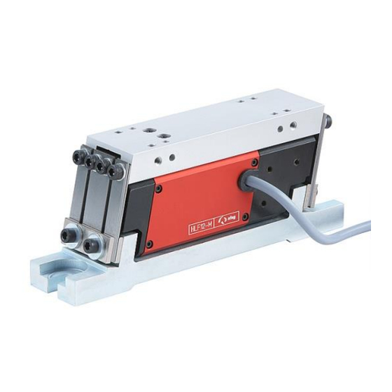
- Page 1 Linear feeder HLF07-M / 12-M / 25-M / 50-M Translation of operating and installation instructions Copyright by Afag GmbH...
- Page 2 This operation instruction applies to: Type Order number 230 V / 50 Hz 50260370 Linear feeder HLF07 115 V / 60 Hz 50270718 230 V / 50 Hz 50259924 Linear feeder HLF12 115 V / 60 Hz 50270770 230 V / 50 Hz 50259276 Linear feeder HLF25...
-
Page 3: Table Of Contents
Table of contents: Safety instructions ....................4 Explanation of symbols and notes ......................4 Basic safety information ........................... 5 1.2.1 Electrical hook up ..........................5 1.2.2 Specific danger points ........................6 Intended use ............................. 6 Notes for Pacemakers and Defibrillators ....................7 Description of the device .................. -
Page 4: Safety Instructions
1 Safety instructions 1.1 Explanation of symbols and notes Symbols: Assembly and commissioning must be carried out by qualified person- nel only and according to these operating instructions. Please observe the meaning of the following symbols and notes. They are grouped into risk levels and classified according to ISO 3864-2. -
Page 5: Basic Safety Information
1.2 Basic safety information Familiarity with these basic safety rules and regulations constitutes the fundamental pre- requisite for safe handling and trouble-free operation of afag HLF linear feeders. These operating instructions contain the most significant regulations for safe HLF opera- tion. -
Page 6: Specific Danger Points
1.2.2 Specific danger points NOTE Afag HLF linear feeders are state-of-the-art equipment designed in compliance with the EU Machinery Directive and accepted safety regulations. Nevertheless, however, risks may arise from using this equipment that may endanger life and limb of user or third parties and cause interference with the HLF or other material as- sets. -
Page 7: Notes For Pacemakers And Defibrillators
1.4 Notes for Pacemakers and Defibrillators Afag vibration conveyors are tested in accordance with regulation 15 of the German Statuto- ry Accident Insurance Association [Deutsche Gesetzliche Unfallversicherung, DGUV] (previ- ously BGV B11 of German Accident Prevention Regulations). The permissible values of ex- posure area 2 are not exceeded, therefore no measures are required pursuant to Section 4 (2) of the DGUV regulation 15. -
Page 8: Description Of The Device
Afag Type HLF-M Linear Feeders are used to remove parts from upstream machines and/or feed parts to downstream machines. Afag Linear Feeders are also used for sort- ing parts, with due consideration of various criteria. Linear feeders are fitted in individual feeding units as well as in complex assembly systems. -
Page 9: Technical Data
2.3 Technical data Figure 1: Dimensions HLF = centre of gravity of useful mass R05.0 16/05/2019 Page 9... - Page 10 The main criterion is the working weight (track length) and the space available for installation. Two Afag Linear Feeder versions are available: 230V/50Hz and 115V/60Hz. Various Afag control devices (see chapter 6.3 Control device) are available for controlling the Linear Feeder. Page 10 16/05/2019 R05.0...
-
Page 11: Assembly Instructions
(see chapter 4.2 Balance of weights). Height adjustments can be achieved by means of appropriate substructures. Standard Afag components are available for setting up complete units. -
Page 12: Mounting Of The Useful Mass
Table 2: Limiting coordinates for the position of the centre of gravity of the working weight. Figure 3: Centre of gravity range Table Limiting coordinates for the position of the centre of gravity of the working weight HLF07-M HLF12-M HLF25-M HLF50-M 85 ± 10 105 ±... - Page 13 Figure 4: Attachment using a side plate O Figure 5: Attachment using a side plate S HINWEIS The useful mass has to correspond to the values specified in chapter 4.2 Balance of weights . R05.0 16/05/2019 Page 13...
-
Page 14: Power Supply
3.4 Power supply WARNUNG ▪ Any work performed on the electrical supply may only be performed by trained, authorised, qualified personnel! ▪ The power supply must be protected by an FI switch (pro- vided by the customer). ▪ The linear feeder may only be operated with the power sup- ply specified on the name plate. -
Page 15: Operating Instructions
Breath [mm] 4.2 Balance of weights The oscillating forces in the base plate of the Afag Linear Feeder are compensated al- most completely due to the principle of opposing oscillations (push-pull). This balance of oscillating forces is however only achieved if: 1. -
Page 16: Fine Adjustment Of Natural Frequency
4.3 Fine adjustment of natural frequency The Afag Linear Feeder is a spring/weight based vibrating system that operates by mak- ing use of resonance. Weights that are not exactly balanced require a spring stiffness modification. - Page 17 Adjustment should be carried out as follows: Put a test part on the feeding track and switch on the control device. Use the turning knob to reduce the feed rate of the Linear Feeder until the part on the feeder track is only moving slowly.
-
Page 18: Setting The Air Gap
4.4 Setting the air gap During series assembly, the air gap of the magnet system is set to the values specified in Table 5. If this air gap deviates from the values specified in Table 5, e.g. after a natural frequency adjustment, then this has to be reset. -
Page 19: Torques
CAUTION Setting an air gap larger than specified may cause the magnet to overheat and the coil to burn out. It is therefore vital that the spec- ified air gaps be adhered to. 4.5 Torques Tightening torques M in Nm for shank screws with metric ISO control threads and head supports according to DIN 912 or DIN 931: Tightening torques M in Nm... -
Page 20: Maintenance Instructions
5 Maintenance Instructions An HLF-M type linear conveyor requires minimal maintenance. Depending on the man- ner in which it is used, signs of wear may occur, which can be compensated for by reset- ting the adjustment plates. Spring wear/ oxidation (increased resonance frequency) Depending on the operating mode and environment, a layer of oxidation may develop on the springs at the contact surfaces which over time may adversely affect the vibration behavior. - Page 21 Foreign part jammed in the air gap be- Remove foreign part tween magnet and rotor Conveyor runs too slowly, there is no movement recognisable Cause of fault Fault repair Supply voltage too low or instable, e.g. Check the supply voltage, readjust the conveyor to only 180 V the existing supply voltage, if necessary Output frequency of the control unit is set...
- Page 22 Change of the system's natural frequency Undo screws of the spring assemblies, check springs, due to a broken spring and replace broken or damaged springs. CAUTION! Cause for a broken spring is often too high oscillation amplitude. --> Check air gap The drive is improperly adjusted, i.e.
-
Page 23: Wear Parts And Spare Parts
5.2 Wear parts and spare parts Table 6: Wear parts Type Designation Order number HLF07 Leaf spring 50203877 HLF12 Leaf spring 50203471 HLF25 Leaf spring 50254134 HLF50 Leaf spring 50411551 Table 7: Spare parts Type Designation Power supply Order number 230V/50Hz 15054450 HLF07... -
Page 24: Accessories
Trimming weight GM50 mass: 50g 50217621 HLF50 Side plate O-50 50197286 Side plate S-50 50217676 6.2 Adjustment aids Table 9: Distance gauge Designation Drive type Order number HLF07-M 50185560 HLF12-M 50185560 Distance gauge HLF25-M 50273499 HLF50-M 50185560 Page 24 16/05/2019 R05.0... -
Page 25: Control Device
Soft-starting, all IRG and MSG types can be mounted in various different ways and offer extra controls for photoelectric barriers, initiator elements, or extern 24VDC signal. For a detailed description of the controllers refer full-range catalogue from AFAG GmbH. Third-party controllers can also be used as long as they meet the technical requirements. -
Page 26: Ordering Address
6.4 Ordering address Germany: Switzerland: Afag GmbH Afag Automation AG Wernher-von-Braun-Straße 1 Zuführtechnik D – 92224 Amberg Fiechtenstrasse 32 CH – 4950 Huttwil Tel.: ++49 (0) 96 21 / 65 0 27-0 Fax: ++49 (0) 96 21 / 65 0 27-390 Tel.: ++41 (0) 62 / 959 86 86...
Need help?
Do you have a question about the HLF07-M and is the answer not in the manual?
Questions and answers