
Related Manuals for iOptron SkyGuider 3550A


Summary of Contents for iOptron SkyGuider 3550A
- Page 1 ® SkyGuider™ Pro Camera Mount Instruction Manual Product #3550, #3550A, #3551 and #3552...
-
Page 2: Table Of Contents
Please don’t charge the battery or use USB power at or below 0°C (32°F), otherwise the rechargeable battery might be permanently damaged. Ver.2.1 iOptron Corp. reserves the rights to revise this instruction without notice. Actual color/contents/design may differ from those described in this instruction. -
Page 3: Skyguider Tm Pro Camera Mount Overview
Pro Camera Mount Overview Pro -- iOptron’s next generation camera tracking device! Leading Introducing The SkyGuider the camera tracker market for nearly four years, iOptron's SkyGuider Pro pushes closer to perfection. Figure 1. SkyGuider Pro mount head only The redesigned SkyGuiderr... - Page 4 Silent tracking for smooth camera motion, perfect for long-term exposures Detachable alt-azi base with fine latitude and azimuth adjusters for easy polar alignment Includes iOptron AccuAlign dark-field illuminated polar scope Adjustable polar scope illumination iPolar electronic polar scope (#3550A only) ...
- Page 5 DEC mounting bracket Counterweight and CW shaft Vixen dovetail saddle for scope mounting Optional ball head available separately (#3305A) Optional tripod (#3221) Optional Go2Nova® 8408 hand controller (#8408) Optional DSLR camera shutter trigger cable...
-
Page 6: Skyguider Tm Pro Camera Mount Assembly
2. SkyGuider Pro Camera Mount Assembly 2.1. Introduction You have just purchased a tracking camera mount that is capable of taking your astrophotography to a new level.. When aligned the polar axis of the SkyGuider Pro camera mount with the celestial North Pole (CNP), or celestial South Pole (CSP), the mount will provide rotation matching the celestial sphere rotation around the Earth. -
Page 7: Assembly Terms
8408 hand controller Or other application/program to calculate the pole star position. Please refer to FAQ session under Support at http://www.ioptron.com for more information. ONLINE CONTENTS (click under “Support” menu) www.iOptron.com This manual Quick Start Guide ... - Page 8 Figure 5. Control panel and ports of a SkyGuider Pro mount head 5- Power switch 10- GUIDE port for ST-4 autoguiding 6- Battery status indicator 11- Camera shutter triggering port 7- Function button 12- Micro USB port 8- Direction button 13- HBX port for optional hand controller 9- Mount status indicator Figure 6.
-
Page 9: Skyguider Tm Pro Camera Mount Assembly
Figure 7. DEC mounting bracket and counterweight package 28- 3/8” Ball head mounting screw 23- Vixen-type dovetail saddle 24- DEC camera mounting block 29- Counterweight shaft 25- DEC base 30- Counterweight shaft safety screw 26- DEC mounting bracket 31- Counterweight 27- Screws for dovetail saddle mounting 2.4. - Page 10 You may use an external battery/power to power the mount through the USB port while using the mount Please don’t charge the battery or use USB power when temperature is at or below 0°C (32°F), otherwise the rechargeable battery might be permanently damaged. If the mount is not to be used for an extended period of time, charge the battery in full and recharge every 6 months.
- Page 11 payload. The latitude adjustment range can be from -30° to 65°. If possible, choose the one with the center of gravity of the system as close to the center of the base as possible. The factory default mounting position is on 30° side. Figure 11.
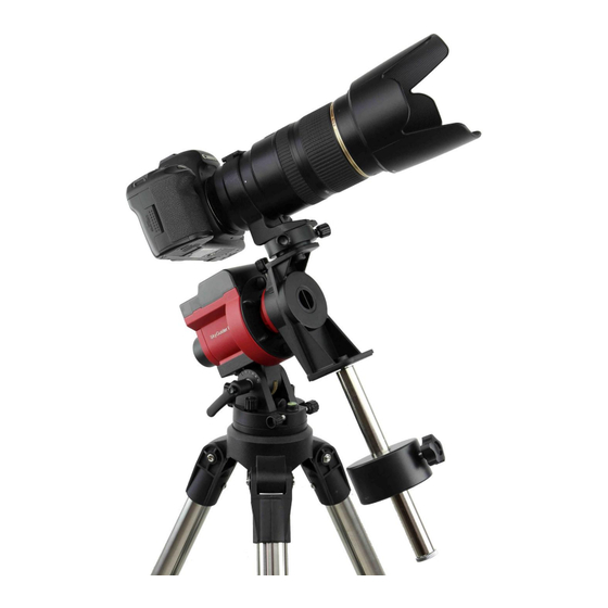
- Page 12 Figure 13. Attach a camera For a heavy DSLR, especially with a long lens (more than 1.5kg or 3.3lbs, including lens) A DEC Mounting Bracket with a counterweight (CW) and CW shaft (or Balance Package) is needed for better balance and performance. To install the DEC Mounting Bracket, remove the Camera Mounting Block from the mount.
- Page 13 Release the RA Clutch Disk by tuning it counterclockwise (CCW) while holding the DEC Mounting Bracket. Slowly move the camera/CW to horizontal position and balance the load in RA direction by moving the CW in or out. More than one CW may be used. Return the mount to upward position and lock the RA Clutch Disk again.
- Page 14 STEP 4. Set the SkyGuider Pro mount Assuming you are using the SkyGuider Pro mount with the alt-azi base and located in northern hemisphere. Face the mount to the true north with assistance of a compass or an electronic compass from your smart phone. Please note that true north is not necessarily aligned to the magnetic north from you compass.
- Page 15 Figure 20. Polar scope app on an iPhone To maximize the benefits of the iOptron polar scope for polar alignment, you need to know where the Polaris is in the northern hemisphere. (or Sigma Octantis in southern hemisphere.) You may find this information via an iPhone/iPad app (iOptron Polar Scope in Apple iTune store). Shown in Figure 20 is a screen shot of an iPhone chart.
- Page 16 Android phone users refer third party Android polar finder (https://play.google.com/store/apps/details?id=com.techhead.polarfinder). You may also use other program/software to calculate the pole star position. Press the power switch on the mount to turn the SkyGuider Pro mount on. Remove metal polar scope cover in the back and polar axis cover in front. (If you are not using the DEC Mounting Bracket, you have to remove the Camera Mounting Block and ball head to expose the polar scope.) Look through the polar scope eyepiece.
- Page 17 Connect a USB cable between the iPolar port on the mount and a computer USB port Calibrate the iPolar Rotation Center (first time use) Click Connect and start polar alignment by following on screen instructions...
-
Page 18: Advanced Applications
3. Advanced Applications The SkyGuider Pro mount is a versatile mount that can be used in many ways. Here are some advanced applications/functions. 3.1. Autoguide The SkyGuider Pro mount is equipped with a ST-4 compatible guiding port to enable autoguiding while tracking. The default guiding speed is (1 ± 0.5X). You may change it from (1 ± 0.1X) to (1 ±... -
Page 19: Dual Camera/Scope Mount
3.3. Dual Camera/Scope Mount The SkyGuider Pro mount is also capable of dual camera/scope mounting as shown below. To maintain a proper balance, you may mount the cameras/scope to DEC mounting bracket with or without extra ball heads, with or without counter weight shaft/CW, with additional accessories. Figure 25. - Page 20 Serial port: connect the HC to a Computer via a RS232 to 4 pin 4 wire (4P4C) RJ9 cable (iOptron item# 8412) for hand controller firmware upgrade. The pin out of the serial port is shown in Figure 27.
-
Page 21: Go2Nova 8408 Hand Controller Function
Firmware Information This function displays the position of the Pole Star for Quick Polar Alignment using the ® iOptron AccuAlign polar scope. In the Northern Hemisphere the position of Polaris is displayed, while in the Southern Hemisphere the position of Sigma Octantis is shown. - Page 22 Polar Star Position Settings Tracking Photography Firmware Information A. Set Time and Site The correct time and coordinates are important to display the Pole star position correctly. Press MENU=>Settings=>Set Time and Site Set Time and Site Set Beep Set Display Set Tracking Rate Press ENTER.
- Page 23 Set Observation Site Coordinate The third and fourth lines display the longitude and latitude coordinates, respectively. “W/E” means western/eastern hemisphere; “N/S” means northern/southern hemisphere; “d” means degree; “m” means minute; and “s” means second. Press ◄ or ► key to move the cursor and using ▲ or ▼ key to toggle between “W” and “E”, “N”...
- Page 24 D. Set Tracking Rate Press MENU => “Settings” => “Set Tracking Rate,” Set Display Set Tracking Rate Set Eyepiece Light Language Then you can select “Solar Rate”, “Lunar Rate”, “0.5 Sidereal Rate” or “Sidereal Rate”. The Mount Status Indicator will reflect the setting changes. Solar Rate Lunar Rate 0.5X Sidereal Rate...
- Page 25 3.4.2.3. Tracking Photography When a supported camera is connected to the mount via a electric shutter trigger cable, the camera can be controlled by the hand controller. You can set the camera Shutter Length, time between each shot (Interval) and total Number of Shots. You may use these images to make time lapse video later.
-
Page 26: Maintenance And Servicing
When mapping the Polaris position from the 24 hrs dial to iOptron polar scope, you need to divide it by 2, i.e. the reading on the dial is 10 o’clock, then you should put the Polaris in your polar scope at 5 o’clock. -
Page 27: Ioptron Customer Service
Department. Customer Service hours are 9:00 AM to 5:00 PM, Eastern Time, Monday through Friday. In the unlikely event that the mount requires factory servicing or repairing, write or call iOptron Customer Service Department first to receive a RMA# before returning the mount to the factory. -
Page 28: Appendix A. Technical Specifications (For #3550 Only)
Appendix A. Technical Specifications (for #3550 only) Mount Compact single axis tracking EQ Payload (MAX) 11 lbs (5kg) Mount weight 2.2 lbs (1kg) with battery Mount weight with base 3.2 lbs (1.450kg) with battery Body material Die-cast aluminum Φ35mm, steel RA shaft Φ88mm, 144 teeth aluminum alloy Worm wheel... -
Page 29: Appendix B. Polar Alignment Using Ipolar Electronic Polarscope
(1) Connect the iPolar Electronic PolarScope to your PC USB port; (2) The iPolar driver will be automatically installed if it is the first time connecting to the computer; (3) You should see “iOptron iPolar” under Camera catalog in computer Device Manager; (4) Goto www.ioptron.com... - Page 30 Click on Take Dark Frame. Follow the instruction on the screen to complete the process. You may check Auto-Load Last Dark Frame box to load the dark frame automatically. However, we recommend to take the dark frame when performing polar align since the temperature difference could have large impact on the alignment.
- Page 31 (4) Enter atmospheric parameters, i.e., temperature and barometric pressure. If the observation site is near equators (lower latitude), or is at high elevation (3000 meter or higher above sea level), please enter the barometric pressure and temperature as precise as possible. Otherwise you may choose default atmospheric settings, just click on Default Atmospheric Parameters.
- Page 32 (5) Click Confirm to complete the location setting. Step 5. Calibration the Camera The calibration process will tell the software if the iPolar is aligned to the mount RA axle after installation. Calibration is only needed when: (1) First time use iPolar; (2) iPolar is adjusted (removed, rotated, etc);...
- Page 33 Camera Center/ RA Axis Virtual Pole When read dot fully covers red cross, the pole alignment is done. NOTE: You can click on Settings and check RAW to see the real sky image at any time. Please uncheck RAW during polar alignment for better results.
-
Page 34: Ioptron One Year Telescope, Mount, And Controller Warranty
Parts or product for which replacement is made shall become the property of iOptron. The customer shall be responsible for all costs of transportation and insurance, both to and from the factory of iOptron, and shall be required to prepay such costs.
Need help?
Do you have a question about the SkyGuider 3550A and is the answer not in the manual?
Questions and answers