Table of Contents
Advertisement
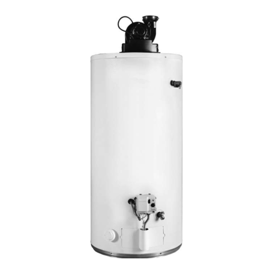
POWER VENTED GAS WATER HEATERS
WARNING: If the information in these instruc-
tions is not followed exactly, a fire or explosion
may result causing property damage, personal
injury or death.
- Do not store or use gasoline or other flam-
mable vapours and liquids in the vicinity of
this or any other appliance.
- WHAT TO DO IF YOU SMELL GAS:
• Do not try to light any appliance.
• Do not touch any electrical switch; do not
use any phone in your building.
• Immediately call your gas supplier from a
neighbor's phone. Follow the gas sup-
plier's instructions.
• If you cannot reach your gas supplier, call
the fire department.
- Installation and service must be performed by
a qualified installer, service agency or the
gas supplier.
ALL TECHNICAL AND WARRANTY QUESTIONS: SHOULD BE DIRECTED TO THE LOCAL DEALER FROM WHOM THE WATER HEATER WAS
PURCHASED. IF YOU ARE UNSUCCESSFUL, PLEASE CONTACT THE COMPANY LISTED ON THE RATING PLATE ON THE WATER HEATER.
1605
KEEP THIS MANUAL IN THE POCKET ON HEATER FOR FUTURE REFERENCE
WHENEVER MAINTENANCE ADJUSTMENT OR SERVICE IS REQUIRED.
Installation and Operating Manual
NOT FOR USE IN MANUFACTURED (MOBILE) HOMES
MODELS GPVX 75L and BTF-80 SERIES 210 , 211
•
AN ODOURANT IS ADDED TO THE GAS USED
BY THIS WATER HEATER.
POWER VENTED GAS MODELS
WITH HOT SURFACE IGNITION
For Your Safety
100271597 / 2000195581 Rev A
•
Advertisement
Table of Contents

Related Manuals for A.O. Smith GPVX 75L Series


Summary of Contents for A.O. Smith GPVX 75L Series
- Page 1 Installation and Operating Manual POWER VENTED GAS WATER HEATERS POWER VENTED GAS MODELS WITH HOT SURFACE IGNITION NOT FOR USE IN MANUFACTURED (MOBILE) HOMES MODELS GPVX 75L and BTF-80 SERIES 210 , 211 WARNING: If the information in these instruc- tions is not followed exactly, a fire or explosion may result causing property damage, personal injury or death.
-
Page 2: Table Of Contents
TABLE OF CONTENTS Safe Installation, Use And Service ....3 Exhaust Venting ......25 General Safety . -
Page 3: Safe Installation, Use And Service
SAFE INSTALLATION, USE AND SERVICE Your safety and the safety of others is extremely important in the installation, use and servicing of this water heater. Many safety-related messages and instructions have been provided in this manual and on your own water heater to warn you and others of a potential injury hazard. -
Page 4: General Safety
GENERAL SAFETY Water temperature over 52°C DANGER (125°F) can cause severe burns instantly resulting in severe injury or death. Children, the elderly and the disabled and are at highest risk of scald injury. Feel water before bathing or showering. Temperature limiting valves are available. - Page 5 GENERAL SAFETY WARNING WARNING Breathing Hazard - Carbon Monoxide Gas • Install vent system in accordance with codes. • Do not operate water heater if flood damaged. • For operation above 3,079 m (10,100’), a high Flammable Vapors altitude orifice must be installed. FLAMMABLES •...
-
Page 6: Introduction
INTRODUCTION Thank You for purchasing this water heater. Properly 2. The installation must conform with these instructions installed and maintained, it should give you years of trouble and local code authority having jurisdiction. In free service. absence of local codes, installation must comply with current editions of the “Natural Gas and Propane Abbreviations found in this Installation and Operating Installation Code”... -
Page 7: Typical Installation
TYPICAL INSTALLATION GET TO KNOW YOUR WATER HEATER - GAS MODELS (LIST REFERENCING FIGURES 1-7) 1 Vent Termination Elbow with Rodent 17 Manifold Door Assembly 36 *Thermal Expansion Tank (required Screen (behind outer door) (see for all closed systems) 2 *Vent Pipe Figure 3 (NG) or Figure 4 (LP)) 37 Aluminum Burner (see Figure 3) 3 *Vent Pipe Coupling (if required) -
Page 8: Replacement Parts And Deliming Products
Natural gas main burner with igniter assembly (item 17 in Figure 1). Flare Figure 6 Vacuum relief valve install per local codes (not supplied with heater). Figure 3 Propane (LP) main burner with igniter assembly (item 17 in Figure 1). Figure 7 Notes: Flare... -
Page 9: Water Piping - Mixing Valve Usage
WATER PIPING - MIXING VALVE USAGE This appliance has been design certified as complying with American National Standard/CSA Standard for water Mixing Valves heaters and certain models with side plumbing connections Water temperature over 52°C DANGER are considered suitable for Water (Potable) Heating and (125°F) can cause severe Space Heating. -
Page 10: Water Heater Operation
Some people are more likely to be permanently injured WATER HEATER OPERATION by hot water than others. These include the elderly, Figure 11 shows the water heater’s sequence of operation children, the infirm and the physically/mentally disabled. when a call for heat is initiated. The ignition control module Table 1 (published by U.S. -
Page 11: Electrical Requirements & Wiring Diagram
ELECTRICAL REQUIREMENTS & WIRING DIAGRAM CAUTION LABEL ALL WIRES PRIOR TO DISCONNECTION WHEN SERVICING CONTROLS. WIRING ERRORS CAN WARNING CAUSE IMPROPER AND DANGEROUS OPERATION. VERIFY PROPER OPERATION AFTER SERVICING. Electric Shock Hazard POWER VENT WIRING SCHEMATIC. Disconnect power before NOTE: REFER TO THE “Installation Checklist” servicing. -
Page 12: Safety Lockouts
SAFETY LOCKOUTS This water heater has several lockout features designed If there is a problem with the wiring of the flammable to prevent the heater from operating in unsafe conditions. vapour sensor or the flammable vapour interface, the LED will flash the failure status code (see “System Status And HIGH LIMIT CONTROLS (ENERGY CUT OFF) Error Codes”). -
Page 13: Locating The New Water Heater
LOCATING THE NEW WATER HEATER FACTS TO CONSIDER ABOUT THE LOCATION Water heater life depends upon water quality, water pressure and the environment in which the water heater Carefully choose an indoor location for the new water is installed. Water heaters are sometimes installed in heater because the placement is a very important locations where leakage may result in property damage, consideration for the safety of the occupants in the building... -
Page 14: Clearances To Combustibles
Clearance for servicing WARNING Adequate clearance of 610mm (24 in.) for servicing this appliance should be considered before installation, such Fire or Explosion Hazard as changing the anodes, etc. • Do not store or use gasoline or other flammable vapours and liquids in the vicinity of this or any other appliance. -
Page 15: Air Requirements
If this water heater will be used in beauty shops, barber shops, cleaning establishments, or self-service laundries with dry cleaning equipment, it is imperative that the water heater or water heaters be installed so that combustion and ventilation air be taken from outside these areas. Propellants of aerosol sprays and volatile compounds, (cleaners, chlorine based chemicals, refrigerants, etc.) in addition to being highly flammable in many cases, will also... -
Page 16: Installing The New Water Heater
INSTALLING THE NEW WATER HEATER WATER PIPING Consult a Qualified Installer or Service Agency. Follow manufacturer’s instructions for installation of valves. Water temperature over 52°C DANGER Before changing the factory setting on thermostat, read (125°F) can cause severe “Operating The Temperature Control System” section in burns instantly resulting in severe injury or death. -
Page 17: Combo Heating
COMBO HEATING 1. Install shut-off valves and unions so that the water heater can be isolated from the heating module should This section serves as a guide for the installation and use servicing of the water heater become necessary. of “Combo” heating systems utilizing a domestic water 2. -
Page 18: Closed Water Systems
CLOSED WATER SYSTEMS SHUT-OFF VALVE HOT-WATER Water supply systems may, because of code requirements OUTLET COLD- or such conditions as high line pressure, among others, WATER INLET have installed devices such as pressure-reducing valves, UNION UNION check valves, and back flow preventers. Devices such as these cause the water system to be a closed system. -
Page 19: Temperature-Pressure Relief Valve
TEMPERATURE-PRESSURE RELIEF VALVE connected to a drain or other suitable means, the water flow may cause property damage. WARNING CAUTION Explosion Hazard Water Damage Hazard • Temperature-pressure relief Temperature-pressure relief valve discharge pipe • valve must comply with ANSI Z21.22-CSA4.4 and ASME must terminate at an adequate drain. -
Page 20: Temperature-Pressure Relief Valve And Pipe
Note: The purpose of a temperature-pressure relief valve HIGH ALTITUDE INSTALLATION is to prevent excessive temperatures and pressures in the storage tank. The T&P valve is not intended for the WARNING constant relief of thermal expansion. A properly sized thermal expansion tank must be installed on all closed systems to control thermal expansion, see “Closed Water Breathing Hazard - Carbon Monoxide Gas Systems”... -
Page 21: Sediment Traps
Make sure the gas supplied is the same type listed on piping system by closing its individual manual shut-off the model rating plate. The inlet gas pressure must not valve during any pressure testing of the gas supply piping exceed 14 inch w.c. for natural gas and propane gas. The system at test pressures equal to or less than 1/2 psi. -
Page 22: Filling The Water Heater
4. Open the cold-water supply valve to the water heater. Notes: • The cold-water supply valve must be left open when SHUT-OFF VALVE HOT-WATER the water heater is in use. OUTLET COLD- • Avoid water leakage when filling the tank. Do not WATER INLET UNION... -
Page 23: Termination Clearances Sidewall Power Vent
TERMINATION CLEARANCES SIDEWALL POWER VENT Note: The following figure and table are intended to illustrate clearance requirements, and do not serve as a substitute for locally adopted installation codes. R N E E C O I N S I D D E T A VENT TERMINAL AIR SUPPLY INLET... -
Page 24: Blower Assembly Installation
BLOWER ASSEMBLY INSTALLATION Ground heater properly. This water heater must be grounded in accordance with the “Canadian 1. This power vented water heater comes with blower Electrical Code” (CSA C22.1), Part I and/or local assembly installed (see Figure 24). codes. These must be followed in all cases. The 2. -
Page 25: Polypropylene Vent Systems
POLYPROPYLENE VENT SYSTEMS make sure the removable cap is installed on the drain port (if a drain hose is not needed). Polypropylene vent systems do not use cement to connect Note: This cap must remain in place if a drain hose is not the pipe and elbow sections but use a push together gasket installed. -
Page 26: Important Notes And Warnings
Important Notes and Warnings Figure 26). How to determine the “equivalent length” is • This heater is certified to be installed using PVC, shown in Figure 27 and in Table 2. CPVC, or polypropylene plastic vent material. Check with your local authorities to determine which materials Vent screen installation are allowed in your area. -
Page 27: Calculating Equivalent Feet
Calculating Equivalent Feet WATER HEATER VENT SIZE PRESSURE MAXIMUM EQUIVALENT MINIMUM EQUIVALENT VENT HEATER INPUT (Inside SWITCH VENT LENGTH LENGTH MODEL (Btu/hr) Diam.) SETTING 50’ (15m) + termination 7’ (2m) + termination elbow and 3” elbow and screen* screen* 75 gal. 76,000 -0.90 in. -
Page 28: Venting Instructions
Venting instructions Note: DO NOT use solvent cement on polypropylene 1. Plan the venting layout starting at the vent termination vent systems. and work back toward the heater. Take into consideration 11. Install the properly sized rodent screen into the outlet the style and position of the vent termination, the vent elbow and secure with corrosion proof screws as pipe routing, elbows and connectors required and the... -
Page 29: Vent Pipe Connection To Blower
CAUTION 75mm (3 in.) TERMINATION MIN. LENGTH MAY BE 90° ELBOW A VENT USED IN A Property Damage Hazard SPECIAL VENTING SYSTEM WITH POSITIVE • Do not overtighten the top and bottom gear clamps of the VENT PRESSURE AND 450mm rubber coupling. -
Page 30: Blower Exhaust Direction
BLOWER EXHAUST DIRECTION The blower assembly may be rotated 90 degree clockwise or counterclockwise to allow horizontal venting in areas having restricted space above the water heater. To rotate the blower outlet, remove the four nuts (with 11/32” nut driver) (see Figure 34), securing the flue collector to the blower housing. -
Page 31: Installation Checklist
INSTALLATION CHECKLIST Note: Use and complete this checklist before lighting the heater. Correct any conditions that do not meet these instructions. Vent Termination Water Heater Location Horizontal Centrally located with the water piping system. 300mm (12”) min. above grade/snow level. Located as close to gas piping and vent pipe system ... -
Page 32: Lighting Instructions
LIGHTING INSTRUCTIONS Read and understand these directions thoroughly before attempting to operate the water heater. Make sure the burner viewport is not missing or damaged. Make sure the tank is completely filled with water before operating the water heater. The gas control valve/thermostat has an “On/Off Switch” and must be turned on before the water heater is operational. Check the label on the front of the water heater near the gas control valve/thermostat for the correct gas. -
Page 33: Operating The Temperature Control System
OPERATING THE TEMPERATURE CONTROL SYSTEM It is recommended that lower water temperatures be used The water heater should be located in an area where to avoid the risk of scalding. It is further recommended, the general public does not have access. If a suitable in all cases, that the water temperature be set for the area is not available, a cover should be installed over the lowest temperature which satisfies your hot-water needs. -
Page 34: Gas Control Valve/Thermostat (160°)
GAS CONTROL VALVE/THERMOSTAT (160°) GAS CONTROL VALVE/THERMOSTAT (181°) 60°C 68°C 74°C 83°C 54°C 60°C 65°C 68°C (140°F) (155°F) (165°F) (181°F) (130°F) (140°F) (150°F) (155°F) 49°C 44°C 21°C 54°C 43°C 21°C BLACK ON/ WHITE ON/ TEMPERATURE TEMPERATURE (120°F) (110°F) (70°F) (130°F) (110°F) (70°F) OFF SWITCH... -
Page 35: For Your Information
FOR YOUR INFORMATION START UP CONDITIONS OPERATIONAL CONDITIONS Condensate Smelly water Whenever the water heater is filled with cold water, some Each water heater contains at least one anode rod for condensate will form while the burner is ON. A water corrosion protection of the tank. -
Page 36: Periodic Maintenance
PERIODIC MAINTENANCE GENERAL UPKEEP If after inspection of the vent system you found sooting or deterioration, something is wrong. Call the local gas utility Make it a habit to look around the heater, the vent piping, to correct the problem and clean or replace the flue and and the hot and cold water pipes. -
Page 37: Burner Operation And Inspection
7. Accessing the blower wheel through the outlet, use BURNER OPERATION AND INSPECTION the paint brush to brush off the outer edge of the Flood damage to a water heater may not be readily visible blower wheel to dislodge any dirt stuck on the blades or immediately detectable. -
Page 38: Combustion Chamber And Burner Cleaning
COMBUSTION CHAMBER AND BURNER CLEANING produced from the presence of hydrogen sulfide gas dissolved in the water. The removal of the anode rod In the event your burner or burner air openings require requires a 1-1/16” socket. cleaning, Call your service agency to remove and clean the burner and correct the problem that required the burner Important: Do not operate the water heater without a to be cleaned. -
Page 39: Temperature-Pressure Relief Valve Test
ANODE ROD * Figure 42 If the Temperature-Pressure Relief Valve on the water heater weeps or discharges periodically, it may be due to thermal expansion. * THE ANODE ROD IS COVERED Note: Excessive water pressure is the most common BY URETHANE FOAM LOCATED cause of temperature-pressure relief valve leakage. -
Page 40: To Drain The Water Heater Storage Tank
To Flush The Water Heater Storage Tank DANGER Follow Step 1 through Step 7 in the “To Drain The Water Heater Storage Tank” section. • Burn hazard. 1. Flush the tank by opening the cold water supply valve • Hot water discharge. and letting the water run until no more sediment drains •... -
Page 41: Leakage Checkpoints
LEAKAGE CHECKPOINTS SERVICE Leakage from other appliances, water lines, or ground seepage should also be checked. If a condition persists or you are uncertain about the To check where threaded portion enters tank, operation of the water heater contact a service agency. insert cotton swab between jacket opening and fitting. -
Page 42: Reference Parts Listing
REFERENCE PARTS LISTING 13 **Combo Heating System Return Inlet 40 Hot-Surface Igniter (see Figure 3) (see Replacement parts may be ordered (Optional) also Figure 46) through your plumber or the local 15 Drain Valve 41 Manifold Door Gasket (see distributor. When ordering replacement 16 Outer Gas Door Figure 3) (see also Figure 46) parts, always have the following... - Page 43 Natural gas main burner with igniter assembly (item 17 in Figure 44). Flare Nut † Figure 49 Note: † For Natural gas models the Flare Nut has Right- hand thread. For Propane models the Flare Nut has Left-hand thread. Figure 46 Propane (LP) main burner with igniter assembly (item 17 in Figure 44).
-
Page 44: Troubleshooting Guidelines
TROUBLESHOOTING GUIDELINES These guidelines should be utilized by a qualified service agent. PROBLEM POSSIBLE CAUSE(S) CORRECTIVE ACTION 1. Air inlets blocked 1. Unblock inlet air openings BURNER FLAME 2. Insufficient secondary air 2. Provide ventilation to water heater TOO HIGH 3. - Page 45 PROBLEM POSSIBLE CAUSE(S) CORRECTIVE ACTION 1. Sulfides in water supply 1. Chlorination procedure 2. Bacteria in water supply 2. Chlorination procedure SMELLY WATER 3. Incompatible anode 3. Replace with anode appropriate for water conditions 1. Filling the new water heater for the first 1.
-
Page 46: Resetting The Heater Control
PROBLEM POSSIBLE CAUSE(S) CORRECTIVE ACTION 1. Air pressure switch not closing due to 1. Determine cause of insufficient insufficient draft – check for: draft. Check draft with manometer at a. Vent piping blocked pressure switch b. Piping length too long a. -
Page 47: Ignition State And Timing
IGNITION STATE AND TIMING LED Flash Control Status Sequence IGNITION STATE TIMING Short flash 5 seconds (NG models) IDLE (no call for heat, Pre-purge once every four 15 seconds (LP models) no fault conditions) seconds Hot Surface Igniter 10 seconds “Heartbeat”, Call For Heat (HSI) Warmup... -
Page 48: Reading The Led Flash Sequence
READING THE LED FLASH SEQUENCE. The LED indicator light is active when the gas valve/thermostat is in operation. The light will normally show a flash sequence of a short flash once every four seconds or a “Heartbeat” of alternating bright/dim. Multiple flash codes indicate an error and can be read as follows: Example: Corrective Action Number 9, Six-Two Flash, three second pause. - Page 49 Corrective Action Corrective Action Number 1. Gas supply is turned off or gas pressure is too low. Ensure supply pressure and manifold gas pressures are within requirements. Manifold pressure is nonadjustable, if gas supply pressure proves correct and manifold pressure is off by more than 0.3” WC replace the control. 2.
-
Page 50: Notes
NOTES 100271597... - Page 51 NOTES 100271597...
- Page 52 599 Hill St. West, Fergus, ON N1M 2X1 Phone: 888-479-8324 • Fax: 519-787-5500 www.hotwater.com...
Need help?
Do you have a question about the GPVX 75L Series and is the answer not in the manual?
Questions and answers