
Related Manuals for Renz C 07


Summary of Contents for Renz C 07
- Page 1 Pace C 07 C 09 C 11 Eine bebilderte PDF-Version der Montageanleitung kann mit dem QR-Code direkt aufgerufen werden.
- Page 2 Pace C 07, C 09, C 11 Tisch-Montage/Table assembly Ø4x20 Rundkopf/Round head Ø4x20 Senkkopf/Countersunk head M10x20 Zylinderkopf/ Cylinder head M6x20 Senkkopf/ Countersunk head 4 x Stellfuß einstellen und kontern. M6x16 Flachkopf/Flat head 4 x Adjust and lock the adjustable foot.
- Page 3 Pace C 07, C 09, C 11 Tisch-Montage/Table assembly Aufbau/Assembly (Es werden 2 Personen benötigt/Two people are required.): Kontrollieren Sie vor der Montage, dass Elektrokabel, Isolierungen und Bauteile nicht beschädigt sind. Bei Beschädi- gungen darf das System nicht an das Stromnetz angeschlossen werden! Check electric cables, isolations and components for intactness before assembly.
- Page 4 Pace C 07, C 09, C 11 Tisch-Montage/Table assembly 2 x Ø 4,0 x 20 mm Tischplatte vorbereiten: Rundkopf. - Handschalter mit 2 Holzschrauben Ø 4,0 x 20 Rundkopf an 2 x Ø 4,0 x 20 mm vorgebohrter Pos. befestigen.
- Page 5 Pace C 07, C 09, C 11 Tisch-Montage/Table assembly Elektrische Steckverbindungen wie folgt verbinden: Connect the plug connectors as follows: A.) TISCHE OHNE ELEKTROLEISTE: TABLES WITHOUT POWER STRIP: Motorkabel (grüne Pfeile) an „M1“ und „M2“+ 1 Kabel Handschalter (blauer Pfeil) in die Steuerung einstecken.
- Page 6 Pace C 07, C 09, C 11 Tisch-Montage/Table assembly Kanal schließen: - Kabel sortiert verlegen, Kanal nach oben/innen gegen die Traverse schwenken und Sperrschlitze gegen die Material- spannung in die gegenüberliegenden Haltenocken einhängen. Innenliegende Kabel nicht einklemmen. 1. Einhängen Close the conduit 2.
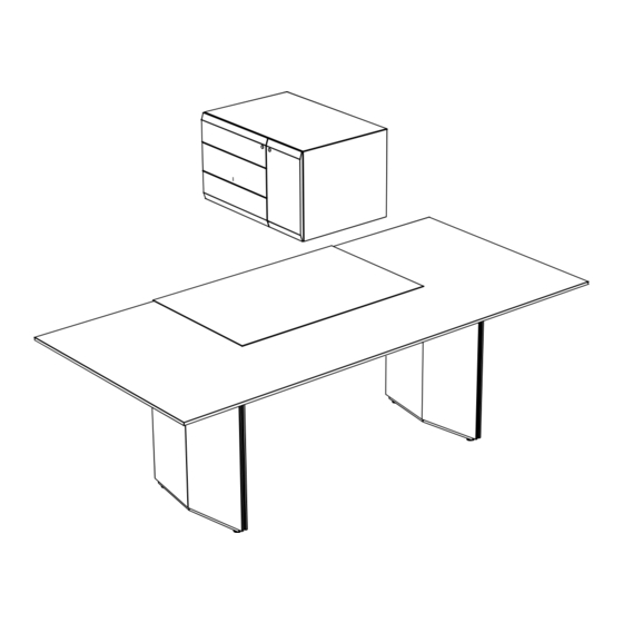
- Page 7 Pace C 07, C 09, C 11 C 63 - C 71 Container C 63 - C 71 Container Verkabelung Cabling Verstellung Zunächst Container exakt ausrichten. Adjustment First align the container accurately. verstellbar Höhenverstellung: Schraube 2 Seitenverstellung: Klemmhebel adjustable leicht lösen und Front über Exzen- 1 leicht nach hinten drücken,...
- Page 8 Wilhelm Renz GmbH + Co. KG Hanns-Klemm-Straße 35 71034 Böblingen Germany T +49 (0)7031.21880 F +49 (0)7031.218850 info@renz.de www.renz.de WEEE-Reg.-Nr.: DE75824099 07_2023...
- Page 9 Pace...
-
Page 10: Table Of Contents
Pace Electrical, height-adjustable office desks This manual is valid for the following models: = Table frame type 1 + table top format 07 (2000 x 1050mm) version 1/07 from 01.03.2015 = Table frame type 1 + table top format 09 (2200 x 1050mm) version 1/09 from 01.03.2015 = Table frame type 1 + table top format 11 (2400 x 1050mm) version 1/11 from 01.03.2015 = Table frame type 2 + table top format 21 (2580 x 1250mm) version 2/21 from 10.02.2016 The enclosed assembly instruction and the operating instructions for the control unit and the manual switch from... -
Page 11: Safety Instructions, Intended Use
Pace Safety instructions, intended use The height adjustability of the undercarriage serves for the electrically operated adjustment of an individual working height for the optionally sitting or standing user of the table by the hand switch,considering the following notes. This product may only be used by children aged 8 years and older, as well as persons with physical, sensory, or mental disabilities or lack of experience and knowledge, if they are supervised or instructed by a responsible person and understand the resulting dangers. - Page 12 In case of damage of the electric cable, the device mustn’t be operated any more. The damaged cable must be replaced by a new, special electric cable delivered by Wilhelm Renz GmbH + Co.KG. (= connection method X). The electric cable is plugged inside the junction box at the lower end of the leg. Install the new cable in the reverse order.
-
Page 13: Technical Data
ATTENTION: By unintended use the manufacturers liability and the general type approval will lapse. Modifications from the factory-made delivery status are not permitted and result into extinction of the liability of Wilhem Renz GmbH + Co.KG. The desk must not be used in humid or corrosive areas or areas exposed to explosion hazards. -
Page 14: Function And Operation
Pace Function and operation, ergonomics The height adjustable desk is is adjustable between 740 and 1140 mm by the hand control. The hand control is at the underside of the tabletop, on the right from the seat. The adjusted table height will be shown on the display. -
Page 15: Function And Operation Of Optional Sliding Leather Desk Pad
Pace Pace Function and operation of optional sliding leather desk pad C41 The sliding leather pad is pulled forward for opening and enables access to the utility compartments and the built-in power strip. ATTENTION: The shut sliding leather pad can be laminary loaded with max. 10kg. The opened pad must not be loaded in any way. Cabling of external accessories Opening the cable channel (basic function in desk C07, C09, C11): The channel is divided lengthways and can be opened from the visitor’s side. -
Page 16: (Art. C42, C44, C45, C46, Desks C07, C09, C11) Cabling Of External Accessories
Pace Electrical box C44: Allows access to the cable channel and the power strip from above. Cabling of external accessories (Meeting table C21) Electrical box C43: Allows access to the cable channel and the power strip from above. Cleaning and care Please note the specifications in the quality pass. -
Page 17: Manufacturer's Manual Logicdata. For Manual Switch
Appendix Manufacturer‘s operating instructions LOGICDATA Operating Instructions Substructure Switch / HSU Handsets MAIN PRODUCT FEATURES 1 memory location keys 2 UP / DOWN keys 3 SAVE key 4 display 1. DURING INSTALLATION Caution - Danger due to electric shocks . HSU handsets are electrical devices. Basic safety precautions must always be taken. - Page 18 Appendix Manufacturer‘s operating instructions LOGICDATA 2. MAINTENANCE All HSU handsets are maintenance-free during their entire service life. - Only use accessories manufactured or approved by LOGICDATA. - Use only spare parts manufactured or approved by LOGICDATA. - Only have repairs or the installation of accessories carried out by qualified persons. - Contact customer service immediately if the system malfunctions The use of non-approved spare parts or accessories may cause damage to the system.
-
Page 19: Manufacturer's Manual Logicdata. For Control Unit
Appendix Manufacturer‘s operating instructions LOGICDATA for control unit 1.1 COMPACT sockets The COMPACT control unit COMPACT-Eco can drive three motors) has the following sockets: 1 Motor socket 1 (M1) 2 Motor socket 2 (M2) 3 Motor socket 3 (M3) S Handswitch socket (HS) P Mains socket F Functional earth, cable lug for earthing the desk frame (6,3x0,8mm lug) D Logic Connector DATA for sensors and cascading... - Page 20 Appendix Manufacturer‘s operating instructions LOGICDATA for control unit 1.3 Connecting the power supply cable 1.4 Commissioning At the beginning of commissioning, the control unit must be initialized. To do this, the „Down“ key on the manual switch must be pressed (approx. 5 sec.) until all motors have reached the lower end position, then the key must be pressed for another approx.
- Page 21 Appendix Manufacturer‘s operating instructions LOGICDATA for control unit 1.3.1 Saving a desktop position This function allows you to save a defined desktop height. One desktop height can be saved per memory position key. To save a position, proceed as follows: Note: if you are switching on the COMPACT control unit for the first time, all the saved positions are set to the lowest desktop height (minimum desktop position).
- Page 22 Appendix Manufacturer‘s operating instructions LOGICDATA for control unit 1.5.3 Changing the desktop height displayed This function enables you to change the height shown on the display, but not the actual position of the desktop. Proceed as follows. 1. Press the memory key. The display will read S –.
- Page 23 Appendix Manufacturer‘s operating instructions LOGICDATA for control unit 1.6.2 Container- and Shelf-Stop positions These 2 features can be used to limit the movement area of the desktop (e.g. if a container is placed underneath the desktop). A container stop position can be defined in the lower half of the movement area, a shelf stop position in the upper half.
-
Page 24: List Of Error Codes, Display
Appendix Trouble Shooting Liste... - Page 25 Appendix Trouble Shooting Liste...
- Page 26 Appendix Manufacturer‘s operating instructions LOGICDATA for control unit...
-
Page 27: Ec Declaration Of Conformity
We hereby declare that the following products in the versions marketed by us comply with the following directives. This declaration shall lose its validity in the event of modification or improper use. Manufacturer: Wilhelm Renz GmbH + Co. KG Hanns-Klemm-Straße 35 71034 Böblingen... - Page 28 We hereby declare that the following products in the versions marketed by us comply with the following directives. This declaration shall lose its validity in the event of modification or improper use. Manufacturer: Wilhelm Renz GmbH + Co. KG Hanns-Klemm-Straße 35 71034 Böblingen...
Need help?
Do you have a question about the C 07 and is the answer not in the manual?
Questions and answers