Table of Contents
Advertisement
Available languages
Available languages
Quick Links
Safe Operation Practices • Set-Up • Operation • Maintenance • Service • Troubleshooting • Warranty
O
'
M
peratOr
s
anual
Log Splitter — 550 Series
WARNING
READ AND FOLLOW ALL SAFETY RULES AND INSTRUCTIONS IN THIS MANUAL
BEFORE ATTEMPTING TO OPERATE THIS MACHINE.
FAILURE TO COMPLY WITH THESE INSTRUCTIONS MAY RESULT IN PERSONAL INJURY.
MTD LLC, P.O. BOX 361131 CLEVELAND, OHIO 44136-0019
Printed In USA
Form No. 769-04107A
(April 2, 2008)
Advertisement
Chapters
Table of Contents

Related Manuals for MTD 24BF550E229


Summary of Contents for MTD 24BF550E229
- Page 1 READ AND FOLLOW ALL SAFETY RULES AND INSTRUCTIONS IN THIS MANUAL BEFORE ATTEMPTING TO OPERATE THIS MACHINE. FAILURE TO COMPLY WITH THESE INSTRUCTIONS MAY RESULT IN PERSONAL INJURY. MTD LLC, P.O. BOX 361131 CLEVELAND, OHIO 44136-0019 Printed In USA Form No. 769-04107A...
-
Page 2: Table Of Contents
Choose from the options below: ◊ Visit us on the web at www.mtdproducts.com ◊ Call a Customer Support Representative at (800) 800-7310 or (330) 220-4683 ◊ Write us at MTD LLC • P.O. Box 361131 • Cleveland, OH • 44136-0019... -
Page 3: Safe Operation Practices
Important Safe Operation Practices WARNING: This symbol points out important safety instructions which, if not followed, could endanger the personal safety and/or property of yourself and others. Read and follow all instructions in this manual before attempting to operate this machine. Failure to comply with these instructions may result in personal injury. - Page 4 This machine should be used for splitting wood only, do Do not operate machine while under the influence of not use it for any other purpose. alcohol, drugs, or medication. Follow the instructions in the manual(s) provided with any Never allow anyone to operate this machine without attachment(s) for this machine.
- Page 5 Spark Arrestor Keep your work area clean. Immediately remove split wood around the machine so you do not stumble over it. WARNING: This machine is equipped with an Do not change the engine governor settings or overspeed internal combustion engine and should not be used the engine.
- Page 6 Safety Symbols This page depicts and describes safety symbols that may appear on this product. Read, understand, and follow all instructions on the machine before attempting to assemble and operate. Symbol Description READ THE OPERATOR’S MANUAL(S) Read, understand, and follow all instructions in the manual(s) before attempting to assemble and operate WARNING—...
-
Page 7: Assembly & Set-Up
Assembly & Set-Up Contents of Carton • One Log Splitter • One Operator’s Manual • One Engine Operator’s Manual • One Tongue Assembly WARNING! Attaching the Tongue Use extreme caution when unpacking this machine. Some components are very heavy and With the log splitter still standing upright, remove the two will require additional people or mechanical hex bolts and hex nuts from the tank bracket. - Page 8 Connecting Cylinder to Beam Disconnect the log cradle from the beam on the side of the control valve. See Fig. 3-5. The log splitter is shipped with the beam in the vertical position. Pull out the vertical beam lock, rotate it back and pivot the Log Cradle Screws beam to the horizontal position until it locks.
- Page 9 Set-Up Check the fluid level using the dipstick. See Fig. 3-7. Do not overfill. Gas and Oil Fill-Up Replace the vented dipstick securely, tightening it until the top of the threads are flush with top of the pipe. Service the engine with gasoline and oil as instructed in the engine manual packed with your log splitter.
-
Page 10: Controls & Features
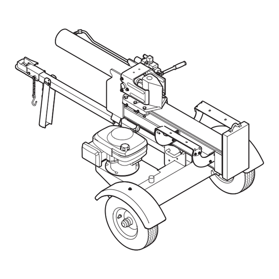
Controls and Features Cylinder Log Dislodger Control Handle Horizontal Beam Lock Tongue Beam Assembly Wedge Jack Stand Cradle Vertical Beam Lock Figure 4-1 Engine Controls Log Dislodger See the Engine Operator’s Manual for the location and function The log dislodger is designed to remove any partially split wood of the controls on the engine. -
Page 11: Operation
Operation Starting the Engine Stopping the Engine Move the choke lever to the OFF position. WARNING! Read, understand and follow all Turn the fuel valve to the OFF position. instructions and warnings on the machine and in this manual before operating. Using the Log Splitter WARNING! Wear leather work gloves, safety shoes,... - Page 12 Stand in front of the log splitter to operate the Stand behind the reservoir tank to operate the control handle and to stabilize the log. See Fig. 5-2. control handle and to stabilize the log. See Fig. 5-4. Figure 5-2 Figure 5-4 To place the beam into the horizontal position proceed as Block the front and back of both wheels.
- Page 13 Operating Tips Support the tongue and pivot the jack stand up against the tongue. See Fig. 5-5. Always: Use clean fluid and check the fluid level regularly. Use an approved hydraulic fluid. Approved fluids include Spring Clip Dexron® III / Mercon® automatic transmission fluid, Pro- Mix™...
-
Page 14: Maintenance & Adjustment
Maintenance & Adjustments WARNING! Allow the fluid to drain into a suitable container. Do not make any adjustments without first stopping the engine, disconnecting the spark Reinsert the filter and refill the reservoir with three (3) plug wire and grounding it against the engine. gallons of oil. - Page 15 Off-Season Storage To lower the beam: Pull out the vertical beam lock on the reservoir tank. If the log splitter will not be used for more than 30 days, prepare Pivot beam lock down to release the beam. it for storage as follows: Carefully pull back on the beam and lower it to the WARNING! Never store the machine with fuel in...
-
Page 16: Service
Service Flexible Pump Coupler Align the pump coupling half with the nylon “spider” by rotating the engine using the starter handle. Slide the The flexible pump coupler is a nylon “spider” insert, located coupling half into place while guiding the three mounting between the pump and the engine shaft. -
Page 17: Troubleshooting
Troubleshooting Problem Cause Remedy Engine fails to start Spark plug wire disconnected. Connect wire to spark plug. Fuel tank empty or stale fuel. Fill tank with clean, fresh gasoline. Choke not in CHOKE position. Move choke to CHOKE position. Faulty spark plug. Clean, adjust gap, or replace. - Page 18 Problem Cause Remedy Slow cylinder shaft speed Gear sections damaged. See authorized service dealer. while extending and Excessive pump inlet vacuum. Make certain pump inlet hoses are clear and retracting unblocked-use short, large diameter inlet hoses. Slow engine speed. See authorized service dealer. Damaged relief valve.
- Page 19 Notes...
-
Page 20: Illustrated Parts List
Illustrated Parts List 5 60... - Page 21 Ref. Part Number Description Ref. Part Number Description 710-0650 Hex Washer Hd. Screw, 5⁄16-18 x .750 718-0769A Hydraulic Cylinder 712-04065 Flange Lock Nut, 3⁄8-16 727-04166 Hydraulic Tube 710-1018 Hex Cap Screw, 1⁄2-20 x 2.75 781-04179 Log Tray 681-04040A Frame Assembly 737-0192 90 Degree Solid Adapter 710-0521...
- Page 22 Notes...
- Page 23 10 — n ectiOn Otes...
- Page 24 MANUFACTURER’S LIMITED WARRANTY FOR The limited warranty set forth below is given by MTD LLC with c. Routine maintenance items such as lubricants, filters, blade respect to new merchandise purchased and used in the United States sharpening, tune-ups, brake adjustments, clutch adjustments,...
- Page 25 LEA Y RESPETE TODAS LAS NORMAS DE SEGURIDAD E INSTRUCCIONES INCLUIDAS EN ESTE MANUAL ANTES DE PONER EN FUNCIONAMIENTO ESTA MÁQUINA. SI NO RESPETA ESTAS INSTRUCCIONES PUEDE PROVOCAR LESIONES PERSONALES. MTD LLC, P.O. BOX 361131 CLEVELAND, OHIO 44136-0019 Impreso en Estados Unidos de América Formulario No. 769-04107A...
- Page 26 Elija entre las opciones que se presentan a continuación: ◊ Visite nuestro sitio web en www.mtdproducts.com ◊ Llame a un representante de Asistencia al Cliente al (800) 800-7310 or (330) 220-4683 ◊ Escríbanos a MTD LLC • P.O. Box 361131 • Cleveland, OH • 44136-0019...
-
Page 27: Medidas Importantes De Seguridad
Medidas importantes de seguridad ADVERTENCIA: La presencia de este símbolo indica que se trata de instrucciones importantes de seguridad que se deben respetar para evitar poner en peligro su seguridad personal y/o material y la de otras personas. Lea y siga todas las instrucciones de este manual antes de poner en funcionamiento esta máquina. - Page 28 Funcionamiento Esta máquina se debe utilizar únicamente para cortar madera, no la use con ningún otro propósito. Antes de arrancar esta máquina, revise las “Instrucciones Siga las instrucciones del(de los) manual(es) entregado(s) de Seguridad”. Si no se respetan estas normas se pueden con cualquier accesorio de esta máquina.
- Page 29 En el caso de troncos que no están cortados en escuadra, Controle todos los protectores y escudos de seguridad el extremo menos cuadrado y la parte más larga del tronco para verificar que se encuentren en posición adecuada. se deben colocar hacia la vigueta y cuña, y el extremo Nunca opere la máquina si se han retirado los protectores o cuadrado se debe ubicar hacia la placa del extremo.
- Page 30 Símbolos De Seguridad Esta página representa y describe los símbolos de seguridad que pueden aparecer en este producto. Leído, entienda, y siga todas las instrucciones en la máquina antes de procurar montar y funcionar. Símbolo Descripción LEA EL MANUAL(S) DEL OPERADOR leído, entienda, y siga todas las instrucciones en el manual(s) antes de procurar montar y funcionar ADVERTENCIA...
-
Page 31: Montaje Y Configuración
Montaje y Configuración Contenido de la caja • Una máquina rompe troncos • Un Manual del operador • Un Manual del operador del motor • Un montaje de lengüeta ¡ADVERTENCIA! Colocación de la lengüeta Tenga mucho cuidado al desembalar esta máquina. Algunos componentes Con la máquina rompe troncos fija en posición vertical, son muy pesados y es necesario que colaboren retire los dos pernos hexagonales y las tuercas hexagonales... - Page 32 Conexión del cilindro a la vigueta Desconecte el bastidor de troncos de la vigueta al costado de la válvula de control. Vea la Fig. 3-5. La máquina rompe troncos se envía con la vigueta en posición vertical. Bastidor de troncos Tire hacia afuera del bloqueo de vigueta vertical, rótelo Tornillos hacia atrás y gire la vigueta a la posición horizontal hasta...
- Page 33 Configuración ¡ADVERTENCIA! Gran parte del líquido original se ha desplazado en el cilindro y las mangueras. Llenado de gasolina y aceite Asegúrese de volver a llenar el depósito para evitar que se dañe la bomba hidráulica. Realice el mantenimiento del motor con gasolina y aceite como Controle el nivel de líquido con la varilla de nivel.
-
Page 34: Controles Y Características
Controles y Características Cilindro Liberador de Manija de la madera control Bloqueo de la viga horizontal Lengüeta Montaje de la vigueta Cuña Gato Bastidor de troncos Vertical: Vigueta Tuerca Figura 4-1 Controles del motor Liberador de la madera Consulte el manual del motor adjunto para ver la ubicación y el El liberador de madera está... -
Page 35: Funcionamiento
Funcionamiento Encendido del motor Detención del motor ¡ADVERTENCIA! Lea, comprenda y siga todas Mueva la palanca de la estrangulación a la posición de las instrucciones y advertencias que aparecen en la reposo. máquina y en este manual antes de operarla. Dé... - Page 36 Párese delante de la unidad para operar la manija de Párese detrás del tanque de depósito para operar la control y estabilizar la madera. Vea la Fig. 5-2. manija de control y estabilizar la madera. Vea la Fig. 5-4. Figura 5-2 Figure 5-4 Para colocar la vigueta en la posición vertical proceda de la siguiente manera:...
- Page 37 Baje la vigueta a la posición horizontal. Asegúrese de que Use un filtro (límpielo o cámbielo regularmente). la vigueta esté trabada firmemente con el bloqueo de Use una tapa de respiradero sobre el depósito de líquido. vigueta horizontal. Asegúrese de que la bomba esté montada y alineada Retire la abrazadera de resorte y la chaveta de horquilla del adecuadamente.
-
Page 38: Mantenimiento Y Ajustes
Mantenimiento y Ajustes ¡ADVERTENCIA! Reinserte el filtro y vuelva a llenar el depósito con tres (3) Siempre detenga el motor, galones de aceite. Entre los líquidos aprobados se incluyen desconecte el cable de la bujía y haga masa contra el el líquido para transmisiones automáticas Dexron®... - Page 39 Almacenamiento fuera de temporada Para bajar la vigueta: Tire del bloqueo de vigueta vertical sobre el tanque de Si el rompe troncos no se usa por más de 30 días, prepárelo para depósito. su almacenamiento de la siguiente manera: Gire el bloqueo de vigueta hacia abajo para liberar la ¡ADVERTENCIA! Nunca almacene la máquina con vigueta.
-
Page 40: Servicio
Servicio Acoplador flexible de la bomba Instale el medio acoplamiento de la bomba y ajústelo sobre el eje de la bomba. Gire el medio acoplamiento hasta El acoplador flexible de la bomba es una pieza de sujeción que el tornillo de fijación quede de frente a la abertura del “araña”... -
Page 41: Solución De Problemas
Solución de Problemas Problema Causa Solución El motor no arranca Se ha desconectado el cable de la bujía. Conecte el cable a la bujía. El depósito de combustible está vacío o el Llene el tanque con gasolina limpia y nueva. combustible se ha echado a perder. - Page 42 Problema Causa Solución Velocidad lenta del eje del Hay partes de los engranajes dañadas. Consulte al distribuidor de servicio autorizado. cilindro durante la extensión o Vacío excesivo en la entrada de la bomba. Asegúrese de que las mangueras de entrada de retracción.
- Page 43 Notas...
- Page 44 MTD. Durante el plazo de la garantía cuchillas, adaptadores para cuchillas, dientes, bolsas para pasto, el único recurso es la reparación o reemplazo del producto como se...
Need help?
Do you have a question about the 24BF550E229 and is the answer not in the manual?
Questions and answers
How do you change the oil
To change the oil on an MTD 24BF550E229:
1. Disconnect the suction hose from the bottom of the reservoir tank.
2. Carefully unthread the inlet filter and clean it with penetrating oil.
3. Reconnect the suction hose and ensure hose clamps are tight.
4. Run the wedge up and down the beam 6 to 8 times using the control handle to circulate and warm the hydraulic fluid.
5. Change the hydraulic fluid in the reservoir every 100 hours of operation.
This answer is automatically generated