Table of Contents
Advertisement
Quick Links
Advertisement
Table of Contents

Related Manuals for TPI 665L


Summary of Contents for TPI 665L
- Page 1 665L Differential Input Logging Manometer Instruction Manual...
-
Page 2: Table Of Contents
TABLE OF CONTENTS INTRODUCTION Congratulations..........3 Product Description ..........3 SAFETY CONSIDERATIONS..........4 TECHNICAL DATA Features and Benefits ........5 Specifications ............6 CONTROLS & FUNCTION S ..........7 . MAKING A MEASUREMENT ........9 SAVING DATA ............10 LOADING SAVED DATA ..........10 MIN / MAX ............10 PRINTING DATA ............10 CHANGING DATE &... -
Page 3: Introduction
A. INTRODUCTION 1. Congratulations!! Thank you for purchasing TPI products. The 665L is easy to use and is built to last. The sensor used in the 665L enables it to perform measurements in non-corro- sive liquid applications. It is backed by a 3 year limited warranty. -
Page 4: Safety Considerations
B. SAFETY CONSIDERATIONS WARNING: Please follow manufacturers test procedures whenever possible. Do not attempt to measure unknown pressures. Damage to the instru- ment may result. GENERAL GUIDELINES ALWAYS • Ensure connections are secure prior to applying pres- sure. • Inspect hoses and fittings for cracks or bends prior to a pressure test. -
Page 5: Technical Data
C. TECHNICAL DATA 1. Features and Benefits Pressure The 665L sensor enables it to be used Sensor in non-corrosive liquid applications. Display 5 digit dual line with backlight Units of Seven units of measure (bar, kPa, Measure PSI, mmHg, inHg, mmH2O, inH2O). -
Page 6: Specifications
2. SPECIFICATIONS Measurement Range: ±101.5 psi (±7bar) Sensor: Can be used in non-corrosive liquid applications Display: 5 Digit Dual line LCD with backlight Input Type: Differential Resolution (max): 0.01 psi (0.001 bar) (0.1 inH2O) Accuracy: 0.2% Full scale Repeatability: 0.1% Full scale Mean Temperature Coefficient: 0.1% of reading per ºC Functions: One Touch Zero, Data Hold, Back-light, Unit Selection, Data Logging, Auto power Off, Min / Max Record,... -
Page 7: Controls & Functions
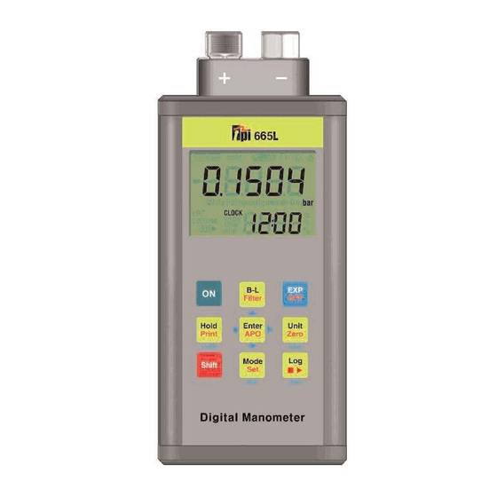
D. CONTROLS & FUNCTIONS IR Ports for PC communica- Input Connectors (1/4” NPT) tion using optional A665L docking station Display IR Port for printing using optional A740 print- Keypad... - Page 8 Press to change the unit of measure. Press the SHIFT key first, then this key to zero the 665L prior to making a measurement. Press to activate shift mode (red key functions). Press to cycle through bottom display modes (percent of fullscale, current time, number of logged readings.
-
Page 9: Making A Measurement
1. Turn the 665L by pressing key. 2. Zero the 665L by pressing 3. Connect the device under test to the “+” port of the 665L. If a differential measurement is being made, connect the other pressure source to the “-” port. -
Page 10: Saving Data
Press to print readings to the optional A740 printer. The 665L will display a 10 second countdown giving you time to align the back holes approximately 4” away from the printer win- dow. “Out” will display and a 9 second countdown will proceed while printing takes place. -
Page 11: Changing Date & Time
J. Changing the Date & Time 1. Activate “EDIT” mode by pressing and “date” is displayed. 2. Press 3. Press to cycle through month, day, and year. 4. Press to change the month, day or year. 5. Once the date has been changed press and “date”... -
Page 12: Logging Data
This mode sets up the interval or time between each logged data point. The interval can be set from 1 second to 24 hours. The 665L can log a total of 5000 data points. NOTE: The optional A665L docking station and software is required to view logged information. - Page 13 This mode sets up start time for automaitc logging. Logging can also be activated manually (See page 12). 1. The logging interval should already be set and the 665L should be displaying “L-Int”. If not, follow steps 1 through 7 on page 12 before proceeding.
- Page 14 (See page 12). 1. The logging interval and start time should already be set and the 665L should be displaying “L-St”. If not, follow steps 1 through 7 on page 12 and steps 1 through 6 on page 13 before proceeding.
- Page 15 K. Logging Data (continued) Deactivating Automatic Logging This mode turns off automatic logging. 1. Activate “EDIT” mode by pressing six times until “L-res” is displayed. 2. Press 3. Press and “L-rES” and “YES” is displayed. 4. Press to cycle between NO (Cancel) and YES (Activate).
-
Page 16: Pc Communication
1. Remove the protective rubber boot beginning at the bot- tom, 2. Using a screwdriver loosen the two screws located at the bottom of the 665L. 3. Pull on the screws to remove the bottom cover/battery holder. 4. Remove the batteries and observing polarity replace them with fresh batteries. -
Page 17: Trouble Shooting And Service
665L still displays “OL” the sensor is no longer working and the 665L needs service. To obtain service for your 665L please return it to: TPI / Attn: Service 9615 SW Allen Blvd Suite 104 Beaverton, OR 97005... -
Page 18: Accessories
O. Accessories Standard Accessories Part Number 1.5 Volt Alkaline Battery (x2) A002 Protective Boot w/ magnets A614 Optional Accessories Part Number USB cradle and software A665... - Page 19 Test Products International, Inc. 9615 SW Allen Blvd., Ste. 104 Beaverton, OR USA 97005 503-520-9197 • Fax: 503-520-1225 info@tpi-thevalueleader.com L270M • 1/25/05 copyright © 2005 Test Products International, Inc.
Need help?
Do you have a question about the 665L and is the answer not in the manual?
Questions and answers