Table of Contents
Advertisement
Quick Links
Advertisement
Table of Contents
Troubleshooting

Related Manuals for Ruud SA14AZ18AJ1NA


Summary of Contents for Ruud SA14AZ18AJ1NA
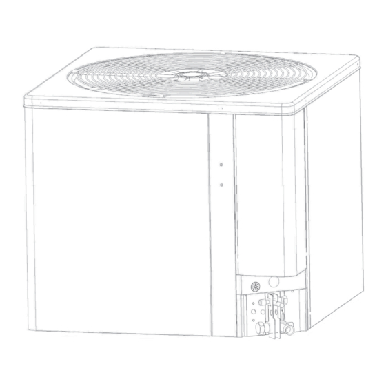
- Page 1 INSTALLATION INSTRUCTIONS 14.3 SEER2 SERIES CONDENSING UNITS 1.5-2.5 TONS FEATURING INDUSTRY STANDARD R-410A REFRIGERANT R-410 NOTE: Appearance of unit may vary. RECOGNIZE THIS SYMBOL AS AN INDICATION OF IMPORTANT SAFETY INFORMATION! ACCREDITED 92-21354-106-02...
-
Page 2: Table Of Contents
CONTENTS 5.0 SYSTEM START-UP & REFRIGERANT CHARGING ........23 1.0 IMPORTANT SAFETY INFORMATION ............3 5.1 System Start-Up Overview ................23 2.0 GENERAL INFORMATION ................4 5.2 Initial System Power-Up ................23 2.1 Introduction ....................4 5.4 Refrigerant Charging ...................24 2.2 Importance of Quality Installation ..............4 5.4.1 Measurement Device Set-Up ..............24 2.3 System Sizing and Selection .................4 5.4.2 Preliminary Charging by Weight ............24... -
Page 3: Important Safety Information
1.0 IMPORTANT SAFETY INFORMATION WARNINGS: CAUTIONS: • R-410A systems operate at approximately 60% higher • These instructions are intended as an aid to pressures (1.6 times) than R-22 systems. Do not use qualified, licensed service personnel for proper R-22 service equipment or components on R-410A installation, adjustment, and operation of this unit. -
Page 4: General Information
2.0 GENERAL INFORMATION • NFPA90B Installation of warm air heating and air WARNING: conditioning systems. Improper installation, or installation not Install the indoor unit in such a way as to allow made in accordance with these instructions, necessary access to the coil/filter rack and blower/ can result in unsatisfactory operation and/ control compartment. -
Page 5: Importance Of Proper Indoor/Outdoor Match-Ups
2.0 GENERAL INFORMATION 2.4 Importance of Proper to Subpart B of Part 430 (Uniform Test Method for Measuring the Energy Consumption of Central Air Indoor/Outdoor Match-Ups Conditioners and Heat Pumps) and the clarifying To assure many years of reliable operation and provisions provided in the AHRI Operations optimum customer comfort and to assure the Manual 210/240 that were applicable at the date... -
Page 6: Unit Specifications
BRAND W = WEATHERKING MP = MAINLINE PERFORMANCE TZ = THERMALZONE 3.2 Available Models Table 1: Available Models CONDENSING UNITS (-)SA14AZ18AJ1NA (-)SA14AZ24AJ1NA (-)SA14AZ30AJ1NA 3.3 Electrical and Physical Data Table 2: Electrical Data and Physical Data ELECTRICAL DATA PHYSICAL DATA Compressor... -
Page 7: Table 3: Dimensions
3.0 UNIT SPECIFICATIONS 3.3 Electrical and Physical Data (cont.) AIR DISCHARGE: ALLOW FIGURE 1 60” [152.4 CM] MINIMUM DIMENSIONS CLEARANCE. A-00008 AIR INLETS (LOUVERED PANELS) ALLOW 6” [15.2 CM] MINIMUM CLEARANCE SERVICE ACCESS ALLOW 24” [61.0 cm] CLEARANCE NOTE: GRILLE APPEARANCE MAY VARY. -
Page 8: Installation
4.0 INSTALLATION 4.1 Tools and Refrigerant 4.1.1 Tools Required for Installing Pressure: The pressure of R-410A is approximately 60% (1.6 times) greater than and Servicing R-410A Models R-22. Recovery and recycle equipment, pumps, Manifold Sets: hoses, and the like must have design pressure –... -
Page 9: Allowable Clearances
4.0 INSTALLATION 4.2 Choosing a Location 4.2.1 Allowable Clearances 4.2.2 Operational Issues Related 12" [30.5 cm] to side intake louvers to Unit Location 24" [61.0 cm] to service access panels IMPORTANT: 60" [152.4 cm] vertical for fan discharge Locate the unit in a If space limitations exist, the following clearances manner that will not prevent, impair, or compromise will have minimal impact to capacity and efficiency... -
Page 10: Corrosive Environment
4.0 INSTALLATION 4.2 Choosing a Location (cont.) 4.2.3 Corrosive Environment WARNING: Disconnect all power to The metal parts of this unit may be subject to rust or unit before starting maintenance. Failure to do so can deterioration if exposed to a corrosive environment. cause electrical shock resulting in severe personal This oxidation could shorten the equipment’s useful injury or death. -
Page 11: Elevating Unit
4.0 INSTALLATION 4.3.3 Elevating Unit WARNING: Secure an elevated unit and its elevating stand in order to prevent tipping. Failure to do so may result in severe personal injury or death. If elevating the unit, either on a flat roof or on a slab, observe the following guidelines. -
Page 12: Replacing Existing Systems
4.0 INSTALLATION 4.4 Refrigerant Line Set Selection 4.4.1 Replacing Existing Systems IMPORTANT: To prevent failure of a new unit, the existing line set When replacing an R-22 must be correctly sized for the new unit and must unit with an R-410A unit, either replace the line set be cleaned or replaced. -
Page 13: Table 5A: Refrigerant Line Sizing Chart (English Units)
Table 5A: Refrigerant Line Sizing Chart (English Units) 14.3 SEER2 Single-Stage Air-Conditioners Equivalent Length (Feet) Apply Long Line Guidelines if Linear Allowable Allowable Line Length < 25 26-50 51-75 76-100 101-125 126-150 151-175 176-200 201-225 226-250 Unit Size Liquid Line Suction Line Exceeds Those Size... -
Page 14: Suction Line Selection
Example: A 3 ton 13 SEER system is installed 50' below the indoor unit, requires a 75' of 1/2" diam eter liquid line, 3/4" diameter suction line, and 4 90° LR elbows, and a filter drier. • Fitting Equivalent Length (ft.) = 4 × .9' + 6' = 9.6’ •... -
Page 15: Maximum Liquid Pressure Drop
4.4.5.4 Maximum Liquid Pressure Drop The total liquid line pressure drop must not exceed 50 psig [345 kPa] to assure a solid column of liquid at the metering device and stable control of superheat. Be sure to account for vertical separation, elbows, filter driers, solenoid valves, sight glasses, and check valves when calculating liquid line pressure drop. -
Page 16: Relative Location Of Indoor And Outdoor Units
4.0 INSTALLATION 4.5 Line Set Installation (cont.) 4.5.2 Relative Location of Indoor and Outdoor Units 4.5.2.1 Indoor and Outdoor Unit Near Same Level OUTDOOR UNIT LEVEL OR NEAR LEVEL TO INDOOR SECTION LINE SET REFERENCE Table 5 FOR MAXIMUM LENGTH LIMITATION IDEALLY, LINE SET SLOPES AWAY FROM OUTDOOR. -
Page 17: Outdoor Unit Below Indoor Unit
4.0 INSTALLATION 4.5 Line Set Installation (cont.) 4.5.2.2 Outdoor Unit Below Indoor Unit OUTDOOR UNIT BELOW INDOOR SECTION LINE SET ROUTE REFRIGERANT LINES EVEN WITH TOP OF COIL OR INSTALL INVERTED TRAP. INSULATE LIQUID LINE IN UNCONDITIONED INSULATE SUCTION SPACE FOR LONG LINE FULL LENGTH LINE APPLICATIONS FOR ALL APPLICATIONS... -
Page 18: Outdoor Unit Above Indoor Unit
4.0 INSTALLATION 4.5 Line Set Installation (cont.) 4.5.2.3 Outdoor Unit Above Indoor Unit INSULATE SUCTION LINE FULL LENGTH FOR ALL APPLICATIONS INSULATE LIQUID LINE IN UNCONDITIONED SPACE FOR LONG LINE APPLICATIONS REFERENCE Table 5 FOR MAXIMUM LENGTH AND VERTICAL SEPARATION LIMITATIONS VERIFY SUB-COOLING... -
Page 19: Tubing Connections
4.0 INSTALLATION 4.5 Line Set Installation (cont.) 4.5.3 Tubing Connections Indoor coils have only a holding charge of dry nitrogen. Keep all tube ends sealed until connections are to be made. • Use type “L” copper refrigeration tubing. Braze the connections with the following alloys: –... -
Page 20: Initial Leak Testing
4.0 INSTALLATION 4.6 Initial Leak Testing 4.7 Evacuation Indoor coils have only a holding charge of dry Evacuation is one of the most important parts of the nitrogen. Keep all tube ends sealed until connections entire installation and service procedure. The life are to be made. -
Page 21: Control Wiring
4.0 INSTALLATION 4.9 Control Wiring WARNING: below to size the 24-volt control wiring. Turn off electric power Do not use phone cord to connect indoor and at the fuse box or service panel before making outdoor units and thermostat. This could damage any electrical connections. -
Page 22: Power Wiring
4.0 INSTALLATION 4.10 Typical Control Wiring Connections (cont.) NOTICE: Field wiring must comply with the Connect power wiring to the line-voltage lugs on the contactor located in the unit electrical box. (See National Electric Code (C.E.C. in Canada) and any wiring diagram attached to unit access panel and applicable local code. -
Page 23: System Start-Up & Refrigerant Charging
5.0 SYSTEM START-UP & REFRIGERANT CHARGING 5.1 System Start-Up Overview space. If they are too small for their intended airflow, they become noisy. If they are not located Once the system hardware and wiring has been properly, drafts can result. Return air grilles must properly installed, the next step is to start the be properly sized to carry air back to the blower. -
Page 24: Refrigerant Charging
5.0 SYSTEM START-UP & REFRIGERANT CHARGING NOTICE: System maintenance is to be l/s = Volts x Amps x 0.895 performed by a qualified and certified technician. SHC x temp rise The optimum refrigerant charge for any outdoor Gas furnaces can use: unit matched with an indoor coil/air handler is affected by the application. -
Page 25: Preliminary Charging By Pressures
5.0 SYSTEM START-UP & REFRIGERANT CHARGING volumetric charging device, adjust the refrigerant the intersection of the installed system and the charge based on the actual line set length. If the outdoor ambient temperature on the Charging entire system has been evacuated, add the total Chart located inside the access panel cover. -
Page 26: R-410A Temperature Pressure Chart
5.0 SYSTEM START-UP & REFRIGERANT CHARGING located within 6" [15.2 cm] outside of the unit on the copper liquid line (small line). It is recommended to use a calibrated clamp-on temperature probe or an insulated surface thermocouple. 4. Subtract the liquid line temperature from the saturation temperature to calculate subcooling. SAT°_____°F [°C] - Liq°_____°F [°C] = SC°_____°F [°C] 5. -
Page 27: Components & Controls
7.0 COMPONENTS & CONTROLS 7.1 Compressor make sure the heater is energized for at least 12 hours before the compressor is started. (Disconnect Scroll compressors are used in all models. switch is on and wall thermostat is off.) Table 11: Maximum System Charge Values 7.2 Fan Motor Size Charge Limit Without Crankcase Heater... -
Page 28: Accessories
8.0 ACCESSORIES 8.4 Low Ambient Control WARNING: Turn off electric power This component senses compressor head at the fuse box or service panel before making any pressure and shuts the outdoor fan off when electrical connections when installing accessories. the head pressure drops to approximately 250 Failure to do so can result in electrical shock, severe personal injury, or death. -
Page 29: Diagnostics & Troubleshooting
9.0 DIAGNOSTICS & TROUBLESHOOTING 9.1 Cooling Mechanical Checks Flowchart... -
Page 30: Diagnostics & Troubleshooting
9.0 DIAGNOSTICS & TROUBLESHOOTING 9.2 General Troubleshooting Guide WARNING: Disconnect all power to unit before servicing. Contactor may break only one side. Failure to shut off power can cause electrical shock resulting in personal injury or death. Table 12: Troubleshooting Guide SYMPTOM POSSIBLE CAUSE REMEDY... -
Page 31: Diagnostics & Troubleshooting
9.0 DIAGNOSTICS & TROUBLESHOOTING 9.3 Service Analyzer Charts Table 13: Service Analyzer Chart COMPRESSOR OVERHEATING SYMPTOM POSSIBLE CAUSE CHECK/REMEDY High superheat Low charge Check system charge. (greater than 15°F Faulty metering device Restricted cap tube, TXV [8.3°C] at coil) Power element superheat out of adjustment internally Foreign matter stopping flow High internal load Hot air (attic) entering return... - Page 32 9.0 DIAGNOSTICS & TROUBLESHOOTING 9.3 Service Analyzer Charts (cont.) COMPRESSOR OVERHEATING (cont.) SYMPTOM POSSIBLE CAUSE CHECK OR REMEDIES Short cycling of Low charge Check system charge. compressor (cont.) Low evaporator airflow Dirty coil Dirty filter Duct too small or restricted Faulty run capacitor Replace.
- Page 33 9.0 DIAGNOSTICS & TROUBLESHOOTING 9.3 Service Analyzer Charts (cont.) CONTAMINATION SYMPTOM POSSIBLE CAUSE REMEDY Moisture Poor evacuation on installation or during service High head pressure Noncondensibles air Unusual head and Wrong refrigerant or mixed refrigerants suction readings Foreign matter – Copper tubing cuttings In each case, the cure is the same.
- Page 34 9.0 DIAGNOSTICS & TROUBLESHOOTING 9.3 Service Analyzer Charts (cont.) FLOODING SYMPTOM POSSIBLE CAUSE REMEDY Loose sensing bulb Secure the bulb and insulate. Bulb in wrong location Relocate bulb. Poor system control using a TXV Wrong size TXV Use correct replacement. Improper superheat setting (less than 5°F [2.8°C]) Replace TXV.
-
Page 35: Troubleshooting Tips
9.0 DIAGNOSTICS & TROUBLESHOOTING 9.3 Service Analyzer Charts (cont.) THERMOSTATIC EXPANSION VALVES (cont.) SYMPTOM POSSIBLE CAUSE REMEDY Refrigerant drainage from flooded evaporator Install trap riser to the top of the evaporator coil. Compressor flood Inoperable crankcase heater or crankcase heater Replace or add crankcase heater. -
Page 36: Outdoor Unit Maintenance
10.0 OUTDOOR UNIT MAINTENANCE 10.1 Outdoor Coil Cleaning The outdoor fan draws air across the coil during an angle. Washing from the top of the coil down operation which results in contaminants collecting from the inside out is the most effective method of on and between the aluminum fins. -
Page 37: Wiring Diagrams
11.0 WIRING DIAGRAMS 11.1 PSC OD FAN MOTOR SINGLE-PHASE WIRING DIAGRAM WIRING DIAGRAM WIRING SCHEMATIC ELECTRICAL BOX (LEFT SIDE) ELECTRICAL BOX (RIGHT SIDE) COMPONENTS OUTSIDE ELECTRICAL BOX COMP WIRE NUTS IN COMP BOX 106079 NO REVISION TO DESIGN, MATERIAL, TOOLING, OR PROCESS IS ACCEPTABLE WITHOUT PRIOR APPROVAL FROM RHEEM THROUGH AN AUTHORIZED CHANGE NOTICE, A REVISED ENGINEERING PTCR 5/25/2022... -
Page 38: Installation Notes
12.0 INSTALLATION NOTES... - Page 39 12.0 INSTALLATION NOTES...
- Page 40 12.0 INSTALLATION NOTES CM 0523...
Need help?
Do you have a question about the SA14AZ18AJ1NA and is the answer not in the manual?
Questions and answers