Table of Contents
Advertisement
Quick Links
5 Input A/V Switcher
with Component Video, Digital Audio, Automatic Input Mode and Volume
Stabilizer
Model VS-502
User Manual
Online Product Registration
http://www.simacorp.com
Package Contents:
1 - VS-502 A/V Switcher Unit
1 - Power Adapter, (120VAC input, 15VDC output)
1 - IR Remote Control, with Batteries
1 - Instruction Manual
Advertisement
Table of Contents

Related Manuals for Sima VS-502

Summary of Contents for Sima VS-502
- Page 1 Component Video, Digital Audio, Automatic Input Mode and Volume Stabilizer Model VS-502 User Manual Online Product Registration http://www.simacorp.com Package Contents: 1 - VS-502 A/V Switcher Unit 1 - Power Adapter, (120VAC input, 15VDC output) 1 - IR Remote Control, with Batteries 1 - Instruction Manual...
-
Page 2: Warning: Changes Or Modifications To This Unit Not Expressly Approved By The Party Responsible For Compliance Could Void The
©2005 by Sima Products Corp. All rights reserved. No part of this publication may be reproduced or transmitted in any form or by any means without prior written permission from Sima Products Corp. Table of Contents PACKAGE CONTENTS: ...1 CAUTION: ...2... -
Page 3: Table Of Contents
FRONT PANEL... 5 REAR PANEL ... 6 IR REMOTE CONTROL... 7 TYPICAL HOOK UP ... 8 OPERATION ... 11 ... 11 OWER ... 11 NPUTS ... 11 NPUT ... 11 OLUME TABILIZER CTIVE OLUME TABILIZATION DJUSTMENT HOW IT WORKS ... 13 ... - Page 4 • Brightness Control - Front panel display allows you to dim the lights for nighttime use (via the remote only). • RS-232C Interface to allow the VS-502 to be controlled by home automation equipment or a PC. (Cable not included) •...
-
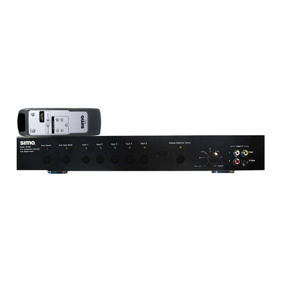
Page 5: Front Panel
LED indicator will light to show the currently selected input. 4 - IR Receive Window Figure 1, VS-502 front panel 5 - Volume Stabilizer Active - Press to turn Volume Stabilizer on or off. The amber indicator light will be lit next to the selected adjustment level. -
Page 6: Rear Panel
DVD, CD player etc. 10 – Optical and Coaxial Output for Digital Audio - Connect the digital output of the VS-502 to the digital audio input of stereo receiver. 11 – RS-232C Connect to your home automation system or PC. -
Page 7: Ir Remote Control
IR Remote Control The IR remote control allows you to control all of the functions available from the unit’s front panel, with the addition of a DIM setting. POWER – Toggles between Active and Standby mode. DIM - Pressing this button cycles through four levels of brightness on the front panel lights-100%, 75%, 50%, 10%. -
Page 8: Typical Hook Up
Option 1: For ease of use, the VS-502 has a composite to S-Video converter. You can feed a combination of composite and S-Video to the VS-502 and feed only a S-Video signal to your TV. This lets you use just one S-Video input on your TV and all sources will automatically be displayed there. - Page 9 Below shows a hook-up with only two input sources. This shows only inputs 3 and 5 being used. The output A from the VS-502 goes to the TV. Note below how component input 3 is being used a composite video input. Video inputs 3 and 4 can both be used as composite or component video inputs.
- Page 10 Input 3 unlike (figure 5) is now being used as a component video input along with a coaxial digital audio connection. The VS-502 component output goes to the TV monitor along with the left and right stereo audio. The digital audio goes to the stereo receiver. Input 1 and 2 are being up- converted from composite and S-Video to component video.
-
Page 11: Operation
If you don’t want the VS-502 to automatically select an active input, turn the Auto Input mode off. Please note when you activate Auto Input mode, it scans the inputs when the VS-502 is on or in the stand-by mode. -
Page 12: Volume Stabilization Adjustment
Volume Stabilization is set to the 10:1 position and the VS ACTIVE light is on. Note: It is normal to notice volume variations even with the VS-502 set to the 10:1 setting. This is due to the fact the human ear is more sensitive to certain frequencies and these will tend to sound louder. -
Page 13: How It Works
Component waiting for a video input. When you turn on a device (VCR, DSS, etc.) a microprocessor in the VS-502 senses the video input, turns on the VS-502 (when it is in the stand-by mode) and selects the input. If a second input occurs, the unit will switch to the new input. If the second input is turned off,... -
Page 14: Volume Stabilization
VS-502 reduces the volume by 9 dB so the output only changes by about 1 dB. Likewise, if the audio signal gets softer by 10 dB, the VS-502 adds gain to the signal so it is only reduced by about 1 dB. -
Page 15: Video Conversion
Video Conversion The VS-502 has special circuitry to convert the composite video inputs to the S-Video outputs and the composite/S-Video signals to component video. Video Input Composite S-Video No Signal Component No Signal Video Input C o m p o s i t e... -
Page 16: Rs-232C Interface
RS-232C Interface The RS-232C interface on the VS-502 lets you connect the unit to a home automation system and control the various functions of the unit. RS-232C Connection The specifications of the RS-232 port are: 9600 baud 1 start, 8 bits, no parity... -
Page 17: Message Acknowledgement
0 = Message received OK 1 = Error The VS-502 will ignore any message that does not begin with the @ character; “01” will be returned. When the VS-502 receives a correctly initiated RS232 message, it will respond with an acknowledgement message, followed by a block of data, as appropriate. - Page 18 1 - 5 = Channel Number 0 = Off 1 = On 0 = Off 1 = On 1 - 4 (1 = Min Level) 0 = Off 1 = On Internal Sima Repair Diagnostics Factory default: 20,1 20,1 20,1 20,1 20,1 Page 18...
-
Page 19: Advanced System Commands
Pressing 1,2,3,4,5 would cause the unit to have the factory default Digital Audio mapping. Factory System Settings Restore At any time the VS-502 can be restored to its factory default settings. 1. Disconnect the VS-502 from AC Power 2. While holding the POWER, AUTO INPUT MODE, and INPUT 1 buttons, reconnect the AC Power to... -
Page 20: Terms
Push STANDBY button so unit is in the ON mode. Your TV is using both composite and S-Video inputs. Use only one or the other to feed into the VS-502 or into your TV. Is the video cable connected from the device to the VS-502? -
Page 21: Technical Specifications
Technical Specifications - Design and specifications are subject to change without notice Audio Inputs, (5 stereo) Input impedance, 47 KΩ Typical input level, 300 mV Frequency response 20 to 20KHz, +/- 3dB (bypass mode) Signal to Noise ratio, greater than 80 dB THD less than 0.03% (bypass mode) Left to right separation, greater than 60 dB Channel to channel separation, greater than 60 dB... -
Page 22: Limited Warranty
Limitation of Liability and Remedies Sima shall have no liability for any damages due to lost profits, loss of use or anticipated benefits, or other incidental, consequential, special or punitive damages arising from the use of, or the inability to use, this product, whether arising out of contract, negligence, tort or under any warranty, even if Sima has been advised of the possibility of such damages. - Page 23 Sima Products Corp. 140 Pennsylvania Avenue, Building #5 Oakmont, PA 15139 USA www.simacorp.com Visit us at www.simacorp.com E-mail us at custserv@simacorp.com Page 23 Manual # 21731...
-
Page 24: System Organization Chart
System Organization Chart Fill in the chart below to help you organize and remember what devices are connected to the inputs and outputs. Save for future reference. From (VCR, DSS, Inputs etc.) To (TV, Receiver, Outputs etc.) View A View B Component Composite Video...
Need help?
Do you have a question about the VS-502 and is the answer not in the manual?
Questions and answers