Lennox SL280UHNV Installation Instructions Manual
Hide thumbs
Also See for SL280UHNV:
- Unit information (53 pages) ,
- Manual (50 pages) ,
- User's information manual (7 pages)
Table of Contents
Advertisement
Quick Links
© 2021 Lennox Industries Inc.
Dallas, Texas USA
THIS MANUAL MUST BE LEFT WITH THE
HOMEOWNER FOR FUTURE REFERENCE
This is a safety alert symbol and should never be
ignored. When you see this symbol on labels or in man-
uals, be alert to the potential for personal injury or death.
Unit Dimensions . . . . . . . . . . . . . . . . . . . . . . . . . . . . . . . . 2
Parts Arrangement . . . . . . . . . . . . . . . . . . . . . . . . . . . . . . 3
SL280UHNV Gas Furnace . . . . . . . . . . . . . . . . . . . . . . . . . 4
Shipping and Packing List . . . . . . . . . . . . . . . . . . . . . . . . 4
Safety Information . . . . . . . . . . . . . . . . . . . . . . . . . . . . . . . 4
Use of Furnace as a Construction Heater . . . . . . . . . . . 5
General . . . . . . . . . . . . . . . . . . . . . . . . . . . . . . . . . . . . . . . . 5
Combustion, Dilution & Ventilation Air . . . . . . . . . . . . . . 6
Setting Equipment . . . . . . . . . . . . . . . . . . . . . . . . . . . . . . . 9
Filters . . . . . . . . . . . . . . . . . . . . . . . . . . . . . . . . . . . . . . . . . . 12
Duct System . . . . . . . . . . . . . . . . . . . . . . . . . . . . . . . . . . . . 12
Venting . . . . . . . . . . . . . . . . . . . . . . . . . . . . . . . . . . . . . . . . 13
Gas Piping . . . . . . . . . . . . . . . . . . . . . . . . . . . . . . . . . . . . . 19
INSTALLATION
INSTRUCTIONS
SL280UHNV
507649-04
08/2021
Supersedes 507649-03
A thermostat is not included and must be ordered
separately.
• A communicating thermostat must be used in
communicating applications.
• In non-communicating applications, the Lennox
ComfortSense
as other non-communicating thermostats.
In all cases, setup is critical to ensure proper system
operation. Field wiring for both communicating and non-
communicating applications is illustrated in diagrams
which begin on page 23
DO NOT use the heat exchanger tubes to lift, drag or
pull the furnace to its installation location.
Doing so will damage the tubes causing noise and or
unsafe operation.
HeatExchanger Tubes
Table of Contents
Electrical . . . . . . . . . . . . . . . . . . . . . . . . . . . . . . . . . . . . . . . 21
Integrated Control. . . . . . . . . . . . . . . . . . . . . . . . . . . . . . . . 31
Blower Performance Data . . . . . . . . . . . . . . . . . . . . . . . . 35
Unit Start-Up . . . . . . . . . . . . . . . . . . . . . . . . . . . . . . . . . . . 39
Proper Combustion . . . . . . . . . . . . . . . . . . . . . . . . . . . . . . 40
Rate Check . . . . . . . . . . . . . . . . . . . . . . . . . . . . . . . . . . . . 40
High Altitude . . . . . . . . . . . . . . . . . . . . . . . . . . . . . . . . . . . . 40
Other Unit Adjustments . . . . . . . . . . . . . . . . . . . . . . . . . . 41
Heating Sequence of Operation . . . . . . . . . . . . . . . . . . . 40
Service . . . . . . . . . . . . . . . . . . . . . . . . . . . . . . . . . . . . . . . . 43
Repair Parts List . . . . . . . . . . . . . . . . . . . . . . . . . . . . . . . . 45
Integrated Control Diagnostic Modes . . . . . . . . . . . . . . . 46
Troubleshooting . . . . . . . . . . . . . . . . . . . . . . . . . . . . . . . . . 53
Page 1
NOTICE
7500 thermostat may be used, as well
®
IMPORTANT
Advertisement
Table of Contents

Related Manuals for Lennox SL280UHNV


Summary of Contents for Lennox SL280UHNV
-
Page 1: Table Of Contents
Parts Arrangement ......3 SL280UHNV Gas Furnace ......4 Blower Performance Data . -
Page 2: Unit Dimensions
Unit Dimensions - inches (mm) ³ GAS PIPING INLET 3-1/8 (79) “A” Width Cabinet NOTE - 60C size units that require air volumes over (Left Side Only) 1800 cfm must have one of the following: 1. Single side return air and Optional Return Air Base with transition that must accommodate required 20 x 25 x 1 inch (508 x 635 x 25 mm) air filter to maintain proper velocity. -
Page 3: Parts Arrangement
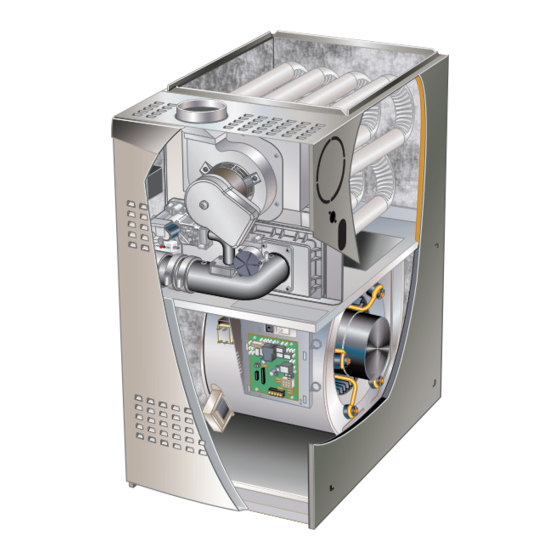
Parts Arrangement Heat Exchanger Combustion Air Inducer Gas Valve Air Intake Pipe Inner Access Control Box Access Panel Panel (includes two-stage integrated control, transformer and circuit breaker) Blower Assembly FIgURE 1 Page 3... -
Page 4: Sl280Uhnv Gas Furnace
Certifications SL280UHNV gas Furnace SL280UHNV units are CSA International certified to ANSI The SL280UHNV gas furnace is equipped with a two- Z21.47. stage, variable speed integrated control. The control is compatible with: In the USA, installation of gas furnaces must conform with Communicating thermostats local building codes. -
Page 5: Use Of Furnace As A Construction Heater
Installed in Combination with a Cooling Coil The SL280UHNV furnace may be installed in alcoves, closets, attics, basements, garages, and utility rooms in When this furnace is used with cooling units, it shall be in- the upflow or horizontal position. -
Page 6: Combustion, Dilution & Ventilation Air
Insufficient tion and ventilation, use the guidelines and procedures in air causes incomplete combustion which can result in car- this section to install SL280UHNV furnaces to ensure ef- bon monoxide. ficient and safe operation. You must consider combustion... - Page 7 Unconfined Space Air from Inside An unconfined space is an area such as a basement or If the confined space that houses the furnace adjoins a large equipment room with a volume greater than 50 cubic space categorized as unconfined, air can be brought in by feet (1.42 m3) per 1,000 Btu (.29 kW) per hour of the com- providing two permanent openings between the two spac- bined input rating of all appliances installed in that space.
- Page 8 EQUIPMENT IN CONFINED SPACE ALL AIR FROM OUTSIDE (Inlet Air from Crawlspace and Outlet Air to Ventilated Attic) CHIMNEY OR GAS VENT VENTILATION LOUVERS (Each end of attic) OUTLET WATER FURNACE HEATER INLET VENTILATION LOUVERS (For unheated crawl space) AIR FLOW NOTE-The inlet and outlet air openings shall each have a free area of at least one square inch (645 ) per 4,000 Btu (1.17 kW) per hour of the total input rating of all equipment in the enclosure.
-
Page 9: Setting Equipment
Doing so will adversely affect the operation of the safety control devices, which could result in personal injury or death. The SL280UHNV gas furnace can be installed as shipped Left Side Right Side in either the upflow position or the horizontal position. - Page 10 Return Air -- Upflow Applications Single Side Return Air Return air can be brought in through the bottom or either (with transition and filter) side of the furnace installed in an upflow application. If the furnace is installed on a platform with bottom return, make an airtight seal between the bottom of the furnace and the platform to ensure that the furnace operates properly and safely.
- Page 11 Removing the Bottom Panel Horizontal Applications Remove the two screws that secure the bottom cap to the The SL280UHNV furnace can be installed in horizontal furnace. Pivot the bottom cap down to release the bottom applications. Order kit number 51W10 (or use equivalent) panel.
-
Page 12: Filters
Before using any filter with this system, check the specifications provided by the filter manufacturer against the data given in the appropriate Lennox Product Specifications bulletin. Additional information is provided in Service and Application Note ACC002 (August 2000). -
Page 13: Venting
Use self-drilling sheet metal screws or a mechanical fas- through the combustion chamber and/or heat exchanger. tener to firmly secure the vent pipe to the round collar of The SL280UHNV is not approved for use with horizontal the flue transition. If self-drilling screws are used to attach venting. - Page 14 IMPORTANT Common Venting Using Metal-Lined Masonry Chimney SEALED SINGLE appliance venting of a fan-assisted furnace into a tile-lined masonry chimney (interior or outside wall) MAX. LENGTH is PROHIBITED. The chimney must first be lined with -- SEE NOTE 1 BELOW. either type B1 vent or an insulated single wall flexible 5 ft.
- Page 15 10% (0.90 x suitable materials, or replaced with a gas vent or chimney maximum listed capacity). suitable for venting SL280UHNV series units. The chim- ney passageway must be checked periodically to ensure 8 - The common venting TABLE 4 and TABLE 5 that it is clear and free of obstructions.
- Page 16 14 - All venting pipe passing through floors, walls, and 18 - The common vent diameter must always be at least ceilings must be installed with the listed clearance as large as the largest vent connector diameter. to combustible materials and be fire stopped 19 - In no case, shall the vent connector be sized more according to local codes.
- Page 17 TABLE 4 Vent Connector Capacity Type B Double-Wall Vents with Type B Double-Wall Connectors Serving Two or More Category I Appliances Vent and Connector Diameter - D (inches) Height Lateral 3 inch 4 inch 5 inch 6 inch Appliance Input Rating in Thousands of Btu Per Hour (feet) (feet) TABLE 5...
- Page 18 Removal of the Furnace from Common Vent 3 - Close all building doors and windows and all doors between the space in which the appliances In the event that an existing furnace is removed from a remaining connected to the common venting system venting system commonly run with separate gas applianc- are located and other spaces of the building.
-
Page 19: Gas Piping
(or top entry in horizontal applications). Connect the gas supply piping into The SL280UHNV is approved for natural gas only. Do the gas valve. The maximum torque is 800 in lbs not attempt to convert and or install in LP propane and minimum torque is 350 in lbs when attaching applications. - Page 20 Left Side Piping MANUAL (Standard) MAIN SHUT-OFF AUTOMATIC MANUAL VALVE GAS VALVE MAIN SHUT-OFF (With 1/8 in. NPT AUTOMATIC VALVE Plugged Tap GAS VALVE (With 1/8 in. NPT Shown) Plugged Tap Shown) GROUND JOINT UNION GROUND JOINT UNION DRIP LEG Right Side Piping FIELD (Alternate)
-
Page 21: Electrical
CAUTION Electrical WARNINg Failure to use properly sized wiring and circuit breaker may result in property damage. Size wiring and circuit Electrostatic discharge can affect breaker(s) per Product Specifications bulletin (EHB) and electronic components. Take care unit rating plate. during unit installation and service to NOTE - Unit nameplate states maximum current draw. - Page 22 9 - Install the room thermostat according to the instructions provided with the thermostat. See table 2 - When the SL280UHNV is running in the heating 8 for field wiring connections in varying applications. mode, the indoor blower will run on the heating...
- Page 23 Communicating Enabled Furnace and Non- Communicating Enabled Furnace and Communicating Outdoor Unit Communicating Enabled Outdoor Unit COMMUNICATING FURNACE COMMUNICATING FURNACE OPTIONAL DISCHARGE AIR SENSOR OPTIONAL DISCHARGE AIR SENSOR OPTIONAL OUTDOOR OPTIONAL COMMUNICATING AIR SENSOR OUTDOOR THERMOSTAT AIR SENSOR COMMUNICATING THERMOSTAT DOOR AIR CONDITIONING OR HEAT PUMP UNIT NON-COMMUNICATING...
- Page 24 Optional Accessories for use with any Communicating System NOTE: ICOMMUNICATING THERMOSTAT SENSES HUMIDITY & CONTROLS HUM CONTACTS TO CYCLE HUMIDIFIER BASED 120V CONNECTIONS “HUM” CONTACT IS QUIRED. CLOSED ANYTIME HUMIDITY DEMAND IS PRESENT TIONS. BUILT INTO ALL COMMUNICATING ENABLED OUT DOOR UNITS).
- Page 25 LENNOX COMMUNICATING OUTDOOR UNIT INDOOR UNIT (1 OR 2 STAGE) FLOAT SWITCH LENNOX COMMUNICATING OUTDOOR UNIT LENNOX COMMUNICATING FURNACE EL296V, SL280V, SL280VN, SL297V, SLP99V cutting DS to R will not cause communication interuption or error code CUT* R-DS W914 Page 25...
- Page 26 TABLE 8 SL280UHNV Field Wiring Applications With Conventional Thermostat DIP Switch Settings and On-Board Links DIP Switch 1 On Board Links Must Be Cut To Select Thermostat Thermostat Wiring Connections System Options Heating Stages 1 Heat / 1 Cool FURNACE...
- Page 27 (Table 8 Continued) SL280UHNV Field Wiring Applications With Conventional Thermostat DIP Switch Settings and On-Board Links DIP Switch 1 On Board Links Must Be Cut To Select Thermostat Thermostat Wiring Connections System Options Heating Stages 2 Heat / 2 Cool...
- Page 28 (Table 8 Continued) SL280UHNV Field Wiring Applications With Conventional Thermostat DIP Switch Settings and On-Board Links DIP Switch 1 Wiring Connections Thermostat On Board Links Must Be Cut To Select Thermostat Heating System Options Stages Dual Fuel FURNACE HEAT PUMP T'STAT TERM.
- Page 29 TABLE 8 (Continued) SL280UHNV Field Wiring Applications With Conventional Thermostat DIP Switch Settings and On-Board Links DIP Switch 1 Wiring Connections Thermostat On Board Links Must Be Cut To Select Thermostat Heating System Options Stages Dual Fuel FURNACE HEAT PUMP T'STAT TERM.
- Page 30 Schematic Wiring Diagram FIgURE 24 Page 30...
-
Page 31: Integrated Control
Integrated Control HS/ CAI LINE 1 NEUTRAL 7 SEGMENT LED FLAME SENSE INDOOR BLOWER DIAGNOSTIC CONNECTOR PUSH BUTTON DIP SWITCHES 12 PIN LOW OUTDOOR AIR VOLTAGE SENSOR CONNECTOR TERMINALS DISCHARGE AIR W915 Y1 TO Y2 SENSOR 2 STAGE COMPR TERMINALS W951 R TO O HEAT PUMP TB83... - Page 32 TABLE 9 Integrated Control DIP Switch Settings - Blower Off Delay Switch Settings Conventional Thermostat (non-communicating) Blower Off Delay SL280UHNV units are equipped with a two-stage, vari- Switch 3 Switch 4 Seconds able speed integrated control. This control manages igni-...
- Page 33 TABLE 12 Ramping Option D Cooling Mode Blower Speed Ramping • Motor runs at 100% until demand is satisfied. • Once demand is met, motor ramps down to stop. Ramping Switch 9 Switch 10 A (Factory) 100% CFM COMPRESSOR DEMAND Switches 11, 12 and 13 -- Heating Mode Blower Speed The switches are factory set to the OFF position which provides factory default heat speed.
- Page 34 On-Board Link W915 2 Stage Compr (Y1 to Y2) On-Board Links Note: In communicating systems with a conventional out- On-board link W915 is a clippable connection between door unit (non-communicating), the on-board clippable terminals Y1 and Y2 on the integrated control. W915 must links must be set to properly configure the system.
-
Page 35: Blower Performance Data
Continuous Fan Only speed is selectable at 28% and 38% of the selected second stage cooling speed - minimum 280 for SL280UH060NVA and 380 cfm for SL280080NV48B. Lennox iHarmony Zoning System Applications - Minimum blower speed is 250 cfm for SL280UH060NV36A and 380 cfm SL280UH080NV48B. - Page 36 First stage COOL (two-stage air conditioning units only) is approximately 70% of the same second stage COOL speed position. Continuous Fan Only speed is selectable at 28% and 38% of the selected second stage cooling speed - minimum 450 cfm. Lennox iHarmony Zoning System Applications - Minimum blower speed is 450 cfm.
- Page 37 - Cut W914 (R to DS) on SureLight® control With Heat Pump - Cut W914 (R to DS) & W951 (R to O) on SureLight® control Dave Lennox ComfortSense® 7500 thermostat to use for this application - Y2081 4 heat / 2 cool *Dehumidification blower speed is 70% of COOL speed for all units .
- Page 38 With Heat Pump - Cut W914 (R to DS) & W951 (R to O) on SureLight® control Dave Lennox ComfortSense® 7500 thermostat to use for this application - Y2081 4 heat / 2 cool *Normal operation first stage cooling blower speed is 70% COOL speed.
-
Page 39: Unit Start-Up
9 - Replace the upper access panel. gas is heavier than air and will settle on the floor. The gas valve on the SL280UHNV unit will be equipped with a gas 10 - Turn on all electrical power to the unit. -
Page 40: Proper Combustion
(Two revolutions assures a ing combustion. Table 19 shows acceptable combustion more accurate time.) Divide by two and compare to time for ALL SL280UHNV models. The maximum carbon in Table 17 below. monoxide reading should not exceed 100 ppm. -
Page 41: Other Unit Adjustments
The two-stage, variable speed integrated control used in fire. The low-fire gas valve continues operation. The SL280UHNV units has an added feature of an internal indoor blower motor is switched to the low-fire heating Watchguard control. The feature serves as an automatic speed. - Page 42 4 - After the 20-second warm-up period has ended, the Applications Using Single-Stage Thermostat gas valve is energized on low fire (first stage) and See Figure 28 for ignition control sequence ignition occurs. At the same time, the control module B - Heating Sequence -- Integrated Control Thermostat sends a signal to begin an indoor blower 30-second Selection DIP Switch 1 ON in “Single-Stage”...
-
Page 43: Service
At the beginning of each heating season, and to comply off operation. with the Lennox Limited Warranty, your system should be 1 - Check the operation of the ignition system, inspect checked by a licensed professional technician (or equiva- and clean flame sensor. - Page 44 Cleaning the Burner 4 - To clean burner and intake debris screen, run a vacuum cleaner over the face of burners. Visually NOTE - Use papers or protective covering in front of the inspect inside the burner. Remove any blockage. furnace during cleaning.
-
Page 45: Repair Parts List
Repair Parts List The following repair parts are available through independent Lennox dealers. When ordering parts, include the complete furnace model number listed on the CSA International nameplate -- Example: SL280UH060NV36A-01. All service must be performed by a licensed professional installer (or equivalent), service agency, or gas supplier. -
Page 46: Integrated Control Diagnostic Modes
Integrated Control Diagnostic Codes Display Action (when button is released) No change (idle)* Remain in idle mode Solid “E” Enter diagnostic recall mode Solid “D” Discharge Air Installed Solid “F” Enter flame signal mode Solid “F” (variable speed only) Program unit capacity size (Unit Code) Two horizontal lines soft disable * No change implies the display will continue to show... - Page 47 Integrated Control Diagnostic Codes Code Diagnostic Codes/Status of Equipment Action Required to Clear and Recover Idle mode (Decimal blinks at 1 Hertz -- 0.5 second ON, 0.5 second OFF). Cubic feet per minute (cfm) setting for indoor blower (1 second ON, 0.5 second OFF) / cfm setting for current mode displayed.
- Page 48 Integrated Control Diagnostic Codes Code Diagnostic Codes/Status of Equipment Action Required to Clear and Recover E124 Active communicating thermostat signal Equipment lost communication with the thermostat. Check missing for more than 3 minutes. four wiring connections, ohm wires and cycle power at the thermostat.
- Page 49 Integrated Control Diagnostic Codes Code Diagnostic Codes/Status of Equipment Action Required to Clear and Recover E206 Gas valve second-stage relay failure Furnace will operate on 1st stage for remainder of the heating demand. Will clear after fault recovered. If un- able to operate 2nd stage, replace control.
- Page 50 Integrated Control Diagnostic Codes Code Diagnostic Codes/Status of Equipment Action Required to Clear and Recover E271 Soft lockout - Exceeded maximum number of re- Check pressure (inches w.c.) of low pressure switch clos- tries. Last retry failed due to the pressure switch ing on heat call.
- Page 51 Integrated Control Diagnostic Codes Code Diagnostic Codes/Status of Equipment Action Required to Clear and Recover E312 Restricted air flow in cooling or continu- Warning Only. Restricted airflow - Indoor blower is running at a re- ous fan mode is lower than cfm setting. duced CFM (Cutback Mode - The variable speed motor has pre-set speed and torque limiters to protect the motor from damage caused by operating outside of design parameters (0 to 0.8”...
- Page 52 Integrated Control Diagnostic Codes Code Diagnostic Codes/Status of Equipment Action Required to Clear and Recover E406 LSOM - Compressor open start circuit. Required amount of current is not passing through Start cur- rent transformer. Clears the error after current is sensed in START sensor, or after power reset.
-
Page 53: Troubleshooting
Troubleshooting: Heating Sequence of Operation CALL FOR FIRST-STAGE HEAT CALL FOR 1ST STAGE HEAT (LOW FIRE) INDOOR BLOWER OFF AFTER HEAT FAN OFF DELAY (LOW HEAT SPEED) INDOOR LIMIT BLOWER OFF HIGH ERROR SWITCH INDOOR WATCHGUARD − AFTER HEAT FAN LIMIT SWITCH CODE CLOSED WITHIN 3... - Page 54 Troubleshooting: Heating Sequence of Operation (Coninued) CALL FOR SECOND-STAGE HEAT CALL FOR 2ND STAGE HEAT (HIGH FIRE) SINGLE STAGE 2 STAGE THERMOSTAT THERMOSTAT 2ND STAGE RECOGNITION DELAY ON DELAY (30 SECONDS) EXPIRED? EXPIRED? ONLY FOR 1ST REQUEST FOR 2ND STAGE HEAT INDUCER SWITCHED TO HIGH SPEED HIGH...
- Page 55 Troubleshooting: Heating Sequence of Operation (Coninued) CALL FOR HEAT SATISFIED FIRST-STAGE HEAT SECOND-STAGE HEAT RUN MODE: 1ST OR 2ND STAGE CALL FOR HEAT. ALL INPUTS MONITORED (LIMIT, PRESSURE, CALL FOR HEAT/COOL, FLAME LEVEL) 2ND STAGE HEAT 2ND STAGE CALL FOR HEAT SATISFIED? DE−ENERGIZE 2ND STAGE GAS VALVE...
- Page 56 Troubleshooting: Cooling Sequence of Operation CALL FOR COOLING 1ST STAGE COOLING REQUEST RECEIVED WAIT FOR COMPRESSOR TIMED OFF DELAY TO EXPIRE ENERGIZE 1ST STAGE COOLING CONTACTOR (COMPRESSOR & FAN) INDOOR BLOWER 2 SECOND ON DELAY ENERGIZE INDOOR BLOWER (LOW COOLING MODE) MAINTAIN INDOOR BLOWER (LOW COOLING MODE)
- Page 57 Troubleshooting: Fan Sequence of Operation CALL FOR FAN CALL FOR FAN INDOOR BLOWER ON CONTINUOUS FAN SPEED CALL FOR FAN MAINTAIN INDOOR BLOWER AT REMOVED? CONTINUOUS FAN REQUEST MAINTAIN INDOOR FOR COOLING GO TO CALL FOR COOLING BLOWER AT RECEIVED? CONTINUOUS FAN REQUEST INDOOR BLOWER OFF...
- Page 58 TABLE 21 Allowable Heating Speeds SL280 -18% -12% Default +12% +18% +24% Model 060NV36A Factory Setting 080NV48B Factory Setting Allowed Allowed Allowed Allowed Allowed Allowed Allowed 080NV60C Factory Setting 100NV60C Factory Setting Not Allowed TABLE 22 Allowable Circulation Speeds Model Number (second stage cool (second stage cool) All Models...
Need help?
Do you have a question about the SL280UHNV and is the answer not in the manual?
Questions and answers