Table of Contents
Advertisement
Quick Links
Operator's Manual
IMPORTANT: Read safety rules and instructions carefully before operating equipment.
Warning:
This unit is equipped with an internal combustion engine and should not be used on or near any unimproved forest-cov-
ered, brush-covered or grass-covered land unless the engine's exhaust system is equipped with a spark arrester meeting applicable
local or state laws (if any). If a spark arrester is used, it should be maintained in effective working order by the operator. In the State
of California the above is required by law (Section 4442 of the California Public Resources Code). Other states may have similar laws.
Federal laws apply on federal lands. A spark arrester for the muffler is available through your nearest engine authorized service dealer
or contact the service department, P.O. Box 361131 Cleveland, Ohio 44136-0019.
PRINTED IN U.S.A.
Troy-Bilt LLC, P.O. BOX 361131 CLEVELAND, OHIO 44136-0019
Self Starter
Mulching Mower
Model 569
FORM NO.
769-00982.fm
(11/2003)
Advertisement
Table of Contents

Subscribe to Our Youtube Channel
Related Manuals for Troy-Bilt Smart Speed 569


Summary of Contents for Troy-Bilt Smart Speed 569
- Page 1 Federal laws apply on federal lands. A spark arrester for the muffler is available through your nearest engine authorized service dealer or contact the service department, P.O. Box 361131 Cleveland, Ohio 44136-0019. Troy-Bilt LLC, P.O. BOX 361131 CLEVELAND, OHIO 44136-0019 769-00982.fm FORM NO.
-
Page 2: Table Of Contents
Customer Support Department or an authorized service dealer. Copy the model number here: Copy the serial number here: TROY-BILT LLC P. O. BOX 3 6 1 1 3 1 www.troybilt.com CLEVELAND, OH 44136... -
Page 3: Important Safe Operation Practices
SECTION 1: IMPORTANT SAFE OPERATION PRACTICES WARNING: This symbol points out important safety instructions which, if not followed, could endanger the personal safety and/or property of yourself and others. Read and follow all instructions in this manual before attempting to operate this machine. Failure to comply with these instructions may result in personal injury. - Page 4 your footing, release the blade control handle 2. Do not mow slopes greater than 15 degrees as immediately and the blade will stop rotating within shown on the slope gauge. three seconds. 3. Do not mow on wet grass. Unstable footing could 9.
- Page 5 9. Never remove gas cap or add fuel while the engine lead to improper performance and compromise is hot or running. Allow engine to cool at least two safety!” minutes before refueling. 4. Mower blades are sharp and can cut. Wrap the 10.
-
Page 6: Slope Gauge
SECTION 2: SLOPE GAUGE Use this page as a guide to determine slopes where you may not operate safely. -
Page 7: Assembling Your Lawn Mower
SECTION 3: ASSEMBLING YOUR LAWN MOWER Tools Required 6. While holding the drive control bar, hook the “Z” end of the drive cable into the bottom hole of the • Pair of Pliers drive control bar from inside to outside. See Figure •... - Page 8 Attaching Drive Adjuster Block Grass Catcher Insert frame Frame The drive adjuster block is attached to the drive cable. into bag 1. Remove bolt attached to the lower left handle. 2. Align the drive adjuster block with hole in handle. Its curved side goes against the handle, 3.
-
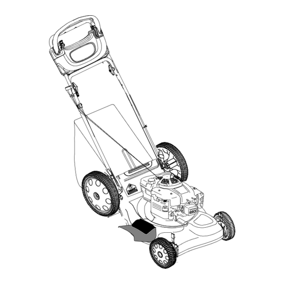
Page 9: Know Your Lawn Mower
Converting To Mulcher Mulching Plug 1. Lift the rear discharge door on the mower and lift the grass catcher up. Release the discharge door to allow it to close the rear opening of the mower. Hinge Pin Converting To Side Discharge Deflector 1. -
Page 10: Operating Your Lawn Mower
Cutting Height Adjustment Lever Start Control Lever These levers are located on each wheel and they are The start control lever is located on the upper right side used to adjust the cutting height. All four levers have to of the upper handle. See Figure 10. The start control be at the same relative position to ensure uniform cut. - Page 11 To De-Energize Self Starter WARNING: NEVER assume starter is in the de-energized mode, even if the key is in • Remove spark plug wire from spark plug. the locked position and or removed from the • Turn safety key to RUN position (1/4 turn engine.
-
Page 12: Maintaining Your Lawn Mower
Bagging Grass Clippings WARNING: If the mower strikes a foreign You can use the grass catcher bag to collect clippings object, stop the engine. Remove spark plug while you are operating the mower. wire from the spark plug and thoroughly inspect for any damage. - Page 13 Lubrication WARNING: When removing the cutting blade for sharpening or replacement, protect Lube hands by using heavy gloves or a thick rag to grasp the cutting blade. 3. Remove the hex bolt which holds the blade adapter-pulley assembly to the engine crankshaft. See Figure 13 .
-
Page 14: Service & Adjustments
SECTION 7: SERVICE & ADJUSTMENTS WARNING: Be sure to disconnect the WARNING: Use a thick piece of rag to spark plug wire and de-energize starter handle the blade while sliding the belt in the before performing any repairs or next step. Make sure the engine does not start maintenance. - Page 15 Adjusting Carburetor 4. Remove the carriage bolts and wing nuts from the handle brackets. Press out on the legs of the lower If the engine is running rough, minor adjustments to the handle. Remove lower handle from the mower. carburetor may be required to compensate for 5.
-
Page 16: Troubleshooting
WARNING: 4. Spread the sides of the lower handle, and push NEVER assume starter is de- it forward and down. energized, even if the key is in the locked • Inspect and replace/sharpen blade, if required. position and or removed from the engine. ALWAYS de-energize starter prior to Engine performing any maintenance or service to... -
Page 17: Illustrated Parts List
SECTION 10: PARTS LIST FOR MODEL F569 Part No. Description 712-0896 Lock Nut 782-7598 Belt Keeper 741-0124 Ball Bearing 750-1050 Flange Bearing 712-3025 Hex Jam Nut 5/16-24 736-0425 Bell Washer.325 x.930 x.45 656-0047 Pulley, 3.82 x.313 x.68 736-0406 Flat Washer.422 x 1.38 x.060 682-0029 Front Idler Assembly 732-04001... - Page 18 Model F569 2 20 60 61 50 51 NOTE: For painted parts, please refer to the list of color codes below. Please add applicable color code, wherever needed, to the part number to order a IMPORTANT: For a proper working machine, use replacement part.
- Page 19 Model F569 Ref. No Part No. Description Ref. No Part No. Description 631-04025 Drive Control Bar: Red 716-0865 Snap Ring 710-0599 TT Screw 1/4-20 x 0.5 717-1762 Gear 14T RH FWD 736-0270 Bell Washer.265 x 0.75 717-1761 Gear 14T LH FWD * 747-04080 Grass Bag Frame 17032A...
-
Page 20: Warranty
MANUFACTURER’S LIMITED WARRANTY FOR: The limited warranty set forth below is given by Troy-Bilt LLC Troy-Bilt does not extend any warranty for products with respect to new merchandise purchased and used in the sold or exported outside of the United States, its United States, its possessions and territories.
Need help?
Do you have a question about the Smart Speed 569 and is the answer not in the manual?
Questions and answers