Table of Contents
Advertisement
®
OPERATOR'S MANUAL
ZERO TURN TRACTOR
Model Numbers
RZT 42 w/42" Mower Deck
RZT 50 w/50" Mower Deck
IMPORTANT:
READ SAFETY
RULES AND INSTRUCTIONS
CAREFULLY
Warning:
This unit is equipped with an internal combustion engine and should not be used oll or near any unimproved forest-
covered, brush-covered
or grass-covered
land unless the engine's exhaust system is equipped with a spark attester meeting
applicable local or state laws (if any). If a spark arrester is used, it should be maintained in effective working order by the operator.
In the State of California the above is required by law (Section 4442 of the California
Public Resources Code). Other states may have
similar laws. Federal laws apply on federal lands. A spark attester for the muffler is available through your nearest engine authorized
service dealer or contact the service department,
P.O. Box 361131 Cleveland, Ohio 44136-0019.
Troy-Bilt LLC, P.O. BOX361131CLEVELAND,0HI0 44136-0019
PRINTED IN U.S.A.
FORM NO. 769-02165
(11/05)
Advertisement
Table of Contents

Related Manuals for Troy-Bilt RZT 42


Summary of Contents for Troy-Bilt RZT 42
- Page 1 ® OPERATOR'S MANUAL ZERO TURN TRACTOR Model Numbers RZT 42 w/42" Mower Deck RZT 50 w/50" Mower Deck IMPORTANT: READ SAFETY RULES AND INSTRUCTIONS CAREFULLY Warning: This unit is equipped with an internal combustion engine and should not be used oll or near any unimproved forest-...
- Page 2 TABLE OF CONTENTS TRACTOR PREPARATION ....................IMPORTANT SAFE OPERATION PRACTICES ..............SAFETY DECALS AND LABELS ................... RECORDING MODEL AND SERIAL NUMBER INFORMATION ........... CUSTOMER SUPPORT ......................SLOPE GAUGE ........................SECTION 1 : CONTROLS AND FEATURES ................ SECTION 2: OPERATION ....................SECTION 3: ADJUSTMENTS ....................
- Page 3 POSITION DRIVE CONTROL LEVERS The tractor is shipped with an activated sealed battery, with the positive battery cable factory connected. The The drive control levers are unfastened from their re- negative cable must be connected. spective pivot brackets and lowered for shipping pur- poses.
- Page 4 WARNING • The engine exhaust, some of its constituents, and certain vehicle components contain or emit chemicals known to the State of California to cause cancer, birth defects or other reproductive harm. • This unit is equipped with an internal combustion engine and should not be used on or near any unimproved forest-covered, brush-covered, or grass-covered land unless the engine's exhaust system is equipped with a...
- Page 5 III. CHILDREN 22. Useonlyaccessories a pproved forthis machine Tragic accidents can occur if the operator is not alert by Troy-Bilt.Read,understand and follow all to the presence of children. Children...
- Page 6 5. Never allow children under 14 years old to After striking a foreign object, stop the engine, operate themachine. C hildren 14yearsandover remove wire from spark plug shouldonly operatethe machineunder close thoroughly inspect the mower for any damage. parental s upervision a ndproperinstruction. Repair damage before...
- Page 7 SAFETY DECALS AND LABELS Keep product safety graphics clean. Replace any safety graphic that is damaged, destroyed, missing, painted over or can no longer be read. Replacement safety graphics are available through your authorized Troy-Bilt dealer. GENERAL SAFETY INSTRUCTIONS GENERAL OPERATING...
- Page 8 SAFETY DECALS AND LABELS RZT50 RZT42 SAFETY GRAPHIC - LOCATED ON LEFT SIDE OF MOWER DECK INFORMATION GRAPHIC - BELT ROUTING LOCATED ON LEFT SIDE OF MOWER DECK...
- Page 9 RECORDING MODEL AND SERIAL NUMBER This Operator's Manual is an important part of your new lawn tractor. It will help you assemble, prepare and maintain the unit for best performance. Please read and understand what it says. Before you start assembling your new equipment, please locate the model plate under the seat of the tractor and copy the information in the space provided below.
- Page 10 USE THIS PAGE AS A GUIDE TO DETERMINE SLOPES WHERE YOU MAY NOT OPERATE SAFELY. SIGHT AND HOLD THIS LEVEL WITH A VERTICAL TREE i<1 A POWER POLE 15 ° WARNING Do not mow on inclines with a slope in excess of 15 degrees (a rise of approximately 2-1/2 feet every 10 feet).
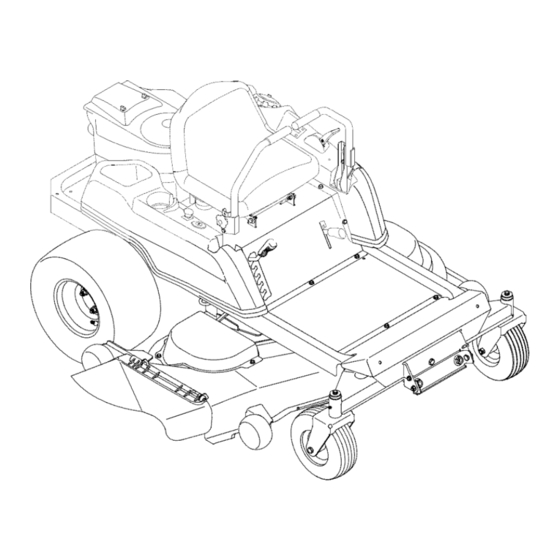
- Page 11 SECTION 1" CONTROLS AND FEATURES \\ \ ¸ Figure 4 A, Deck Height Index H, Storage Tray B, Deck Lift Handle J. Seat Adjustment Lever (Not Seen) C, RH and LH Drive Control Levers K. Fuel Tank Cap L. Hour Meter/Indicator Panel D, Ignition Switch E.
- Page 12 NOTE: References to LEFT, RIGHT, FRONT, and NOTE: To prevent accidental starting and/or battery discharge, remove the key from the ignition switch REAR indicate that position on the tractor when when the tractor is not in use. facing forward while seated in the operator's seat. Deck Height Index Power Take-Off (PTO) Switch The deck height index consists of six index notches...
- Page 13 Do not run the Battery_ -,-0 D Oil Pressure Indicator --Indicator engine while this indicator is illuminated. Contact RZT50 only your authorized Troy-Bilt Service Dealer to have the tractor and engine inspected. Hour NOTE: The oil pressure indicator may illuminate --Meter when the ignition switch is in the ON position, should turn off when the engine is started.
- Page 14 M. ThrottleControl Model RZT42 ONLY When starting engine, push the control handle fully forward into Thethrottlecontrolis locatedon the LH consoleto "CHOKE" position. Figure After the leftof the operator's seat.Whenset in a given starting warming engine, move position, a uniform engine speed willbemaintained. control handle rearward until you feel it move...
- Page 15 • Do not operate the tractor with the mower deck Contact your authorized Troy-Bilt Service Dealer. removed. Removal of the deck will change the • The safety interlock system prevents the engine balance of the tractor, and could contribute to a tractor rollover.
- Page 16 Have the tractor inspected by your authorized detent position. Do not use the choke to enrich Troy-Bilt Service Dealer dealer. the fuel mixture, except as necessary to start the engine.
- Page 17 COLDWEATHER STARTING • Turn the ignition key to the "OFF" position and Be sure to use the proper oil for the expected remove the key from the ignition switch. temperatures (checkthetablein theenginemanual). NOTE: Always remove the key from the ignition Follow the normal e nginestarting instructions a bove.
- Page 18 • Move the RH and LH drive control levers inward DRIVING FORWARD in the neutral position. See Figure 10. Faster Control Lever Moved Inward and in Neutral Slower Neutral Position Figure 11 Figure 10 • slow the tractor move the controls lever rearward to attain the desired speed, or move the...
- Page 19 - Toturntothe right,movetherightdrivecontrol IMPORTANT: Always maintain your grasp on the leverrearward oftheleftlever. S eeFigure 13. drive control levers. Do not release the levers to slow the tractor or to return to neutral. FORWARD RIGHT TURN Turning While Driving Rearward • To turn the tractor while driving rearward, move the control levers as necessary so that one lever is forward of the other.
- Page 20 STOPPING THE TRACTOR Executing a Zero Turn • Move both drive control levers to the neutral position to stop the motion of the tractor. tractor MUST STOPPED. WARNING: When executing a zero turn, • Push switch downward Executing a zero turn while the tractor is moving significantly reduce...
- Page 21 Troy-Bilt Service Dealer to have the tractor inspected. DO NOT operate the tractor if any safety circuit is not • On the first pass pick a point on the opposite side of the area to be mowed.
- Page 22 SECTION 3: ADJUSTMENTS ADJUSTING THE OPERATORS SEAT • Insert the carriage bolt through the pivot bracket and control lever slot. Slide the bell washer onto • To adjust the position of the seat, move and hold the bolt and screw on the nut knob, but do not the seat adjustment lever toward the left.
- Page 23 Remove the hex cap screw and sems nut secur- service work on the hydrostatic transmissions should ing the black negative battery lead to the negative be performed by your authorized Troy-Bilt Service battery post (marked NEG). Move the cable away Dealer. from the negative battery post. •...
- Page 24 • Charge the battery witha 12-volt b attery charger If you have a recurring problem with blown fuses, ata MAXIMUM rateof 10amps. have the tractor's electrical system checked by your authorized Troy-Bilt Service Dealer. Voltmeter State of Charging Reading Charge Time 12.7...
- Page 25 Figure 23 withdraw the ferrule. Wheel rotation should stop. If it does not, contact your authorized Troy-Bilt • After moving the tractor, disengage both bypass Service Dealer. rods. Lift the rod and guide the flange of the rod •...
- Page 26 TRACTOR HIGH SPEED TRACKING TRANSMISSION DRIVE BELT Ifthe tractor t rackstoonesidewithbothdrivecontrol If the transmission drive belt becomes worn and levers fully forward,adjust the controllevers as causes the drive transmissions to slip, the drive belt follows: must be replaced. To replace the drive belt, proceed as follows: Checkfor properand balanced air pressure •...
- Page 27 TRACTOR STORAGE Emptying the fuel system: • Prior to putting the tractor in storage, monitor If your tractor is not going to be operated for an fuel consumption with the goal of running the extended period of time (thirty days to approximately fuel tank empty.
- Page 28 SECTION 5: MOWER DECK This section contains removal, installation, adjust- Rolling the belt off the PTO pulley. ment, and maintenance information for the 42-inch • Using the deck lift handle, raise the deck to the (RZT42) and 50-inch (RZT50) mower decks. upper position that allows for the most horizontal run of the belt between the deck idler pulleys and DECK REMOVAL...
- Page 29 7. Slide the deck forwardso that the deck front • Route the backside of the belt around the fixed hanger r odcanbeliftedoutofthetwoslotsofthe idler pulley of the deck. Refer to Figure 27. frontdeckbracket. A fter liftingthe fronthanger • Working from the middle of the tractor, pivot the rod out of the slots,slidethe deckrearward so idler bracket/movable pulley rearward against the...
- Page 30 LEVELING THEMOWER DECK - Retighten the hex cap screw on the right deck Whenleveledcorrectlythe mowerdeck shouldbe hanger bracket when proper adjustment achieved. levelsideto side,andshouldbe approximately a 1/8 to1/4inchlowerinthefrontofthedeck. RZT50 - 50 Inch Deck ONLY Sideto SideLeveling - Loosen, but do not remove, the hex cap screw If thecuttingdeckappears to bemowing unevenly, a on the left deck hanger bracket.
- Page 31 • Fromthe front of the tractor,loosenthe outer NOTE: The deck gauge wheels are an anti-scalp nutson thedeckfronthangerrod,andturnthem feature of the deck and are not designed to support the awayfromtheinnernuts.SeeFigure 32. weight of the cutting deck. Using the lift handle, set the deck in the desired height setting, then check the gauge wheel and if Hex Nuts necessary adjust as follows.
- Page 32 DECK MAINTENANCE Use a 15/16 inch wrench to hold the hex nut on top of the spindle assembly when loosening the Cleaning And Blade Care hex nut securing the blade. A block of wood may WARNING: Before performing any main- be placed between the deck housing and the tenance,...
- Page 33 DECK LUBRICATION REPLACING THE DECK DRIVE BELT • Remove the deck from beneath the tractor, (refer • After every 10 hours of operation and/or before to Deck Removal on page 28). putting the deck into winter storage, lubricate spindle assemblies with •...
- Page 34 SECTION 6: PARTS LIST RZT42 AND RZT50 REF. PART NUMBER DESCRIPTION QTY, 603-04303B Frame Assembly ......777122489 Graphic, Release Lever ....703-05829 Idler Arm, Drive ....... 710-0520 Screw, Hex Cap, 3/8-16 x 1.5 GR5 710-3005 Screw, Hex Cap, 3/8-16 x 1.25 GR5 712-04065 Nut, Hx Insert Flnge Lck, 3/-16 GrF 732-0626...
- Page 35 MODELS RZT42 AND RZT50 REF. PART FIEF. PART NUMBER DESCRIPTION QTY. NO. DESCRIPTION QTY. NUMBER 710-1268 Screw, Hx. Wash. Hd. Tapp .... 736-0275 Washer, Flat, .344 x .688 x .065 ..#10-16 x .375 736-3019 Washer, Flat, .531 x 1.062 x .134 HT 712-04063 Nut, Hx Insert Flange Lck ....
- Page 36 MODELS RZT42 AND RZT50 Section of Main Wire Harness (Reference Only)
- Page 37 MODELS RZT42 AND RZT50 REF, PART NUMBER DESCRIPTION QTY, 710-0227 Screw, Hex Wash. Hd. Tapp .... #8-18 x .5 710-0599 Screw, Hex Wash. Hd. Tapp .... 1/4-20 x .5 710-3015 Screw, Hex Cap, 1/4-20 x .75 GR5 .. 712-0271 Nut, Hex Sems, 1/4-20 ..... 725-04022A Meter, Hour ........
- Page 38 MODELS RZT42 AND RZT50...
- Page 39 777S32354 Graphic, Warning ......777122307 Graphic, Deck Height ..... 703-05373A Bracket, Foot Rest ......777D09987 Graphic, Troy-Bilt ......703-05467 Bracket, Switch Mounting ....710-04261 Screw, Hex Wash. Hd Tapp ....#12-16 x .50 710-0599 Screw, Hex Wash. Hal. Tapp .....
- Page 40 MODELS RZT42 AND RZT50...
- Page 41 MODELS RZT42 AND RZT50 REF. PART NUMBER DESCRIPTION QTY. 603-04160A Shaft Assembly, Deck Lift ....603-04322 Lever, Lapbar, RH ....... 603-04324 Lever, Lapbar, LH ....... 703-05387A Bracket, Lapbar Pivot ......703-05396 Handle, Brake ........703-05414A Bracket, Front Deck Hanger ....703-05793 Arm, Deck Lift ........
- Page 42 MODEL RZT42...
- Page 43 MODEL RZT42 FIEF. PART NUMBER DESCRIPTION QTY. 603-04156 Bracket, Deck Lift ......603-04335 Housing, Deck ........777S32599 Graphic, Danger ......777S30503 Graphic, Danger ......777122281 Graphic, Instruction ....... 618-0427 Spindle Assembly ......756-1188 Pulley ..........703-05824 Arm, Idler .......... 710-0347 Screw, Hex Cap, 3/8-16 x 1.75 GR5 710-0528 Screw, Hex Cap, 5/16-18 x 1.25 GR5...
- Page 44 MODEL RZT50 ½...
- Page 45 MODEL RZT50 REF. PART NUMBER DESCRIPTION QTY. 603-04328 Housing, Deck ........777S32598 Graphic, Danger ....... 777S30503 Graphic, Danger ....... 777122282 Graphic, Instruction ......618-04126 Spindle Assembly ........ 756-1171 Pulley, 5.39 Dia ........ 737-3000 Fitting, Lube, 3/16 Drive ....631-04070 Chute Assembly, Discharge ....
- Page 46 MODEL RZT42...
- Page 47 MODEL RZT42 REF. PART NUMBER DESCRIPTION QTY. 603-04176 Tube, Exhaust ........751-10057C Tank, Fuel, 3.0 Gal ......751-3124B Cap, Fuel ........703-05441A Bracket, Muffler Mounting ....' 703-05870 Shield, Muffler Tube Heat ....710-0227 Screw, Hex Wash. Hd. Tapp .... #8-18 x .5 710-04248 Screw, Hex Cap, 7/16-20 x 4.0 GR5...
- Page 48 MODEL RZT50...
- Page 49 MODEL RZT50 REF. PART NUMBER DESCRIPTION QTY. 603-04162 Tube, Exhaust RH ......603-04163 Tube, Exhaust LH ......751-10057C Tank, Fuel, 3.0 Gal ......703-05441A Bracket, Muffler Mounting ....710-0227 Screw, Hex Wash. Hd. Tapp ..... #8-18 x .5 710-04248 Screw, Hex Cap, 7/16-20 x 4.0 GR5 710-0599 Screw, Hex Wash.
- Page 50 MODELS RZT42 AND RZT50 REF. PART REF, PART NUMBER DESCRIPTION QTY. NUMBER DESCRIPTION QTY, 618-04326 Nut, Hex Lock, 9/16-18 GRC .... Transmission Assembly, RH ... 712-04088 618-04327 Transmission Assembly, LH .... 712-0459 Nut, Hex Flange Lock, 7/16-20 GrB 634-04127 RZT42 Wheel Assembly, 18 x 6.5 x 8 712-3050 Nut, Lug, 7/16-14 ......
- Page 51 NOTES...
- Page 52 MANUFACTURER'S LIMITED WARRANTY FOR" ® The limited warranty set forth below is given by Troy-Bilt LLC Troy-BiIt does not extend any warranty for products with respect to new merchandise purchased and used in the sotd or exported outside of the United States, its United States, its possessions and territories.
Need help?
Do you have a question about the RZT 42 and is the answer not in the manual?
Questions and answers