Table of Contents
Advertisement
®
Hygenic
Fully cleanable Recovery
Tank
®
TennantTrue
Parts
®
IRIS
a Tennant Technology
®
Pro-Panel
Controls
™
Smart-Fill
Automatic Battery Watering
™
Insta-Click
Magnetic Disk
For the latest Parts Manuals and other
language Operator Manuals, visit:
www.tennantco.com/manuals
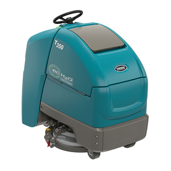
T350
Stand-On Rider Scrubber
Service Information
*9016422*
English EN
Manual
9016422
Rev. 00 (12-2017)
R
Advertisement
Table of Contents
Troubleshooting

Related Manuals for Tennant ec H2O NanoClean T350


Summary of Contents for Tennant ec H2O NanoClean T350
- Page 1 English EN Service Information Manual ® Hygenic Fully cleanable Recovery Tank ® TennantTrue Parts ® IRIS a Tennant Technology ® Pro-Panel Controls ™ Smart-Fill Automatic Battery Watering ™ Insta-Click Magnetic Disk 9016422 For the latest Parts Manuals and other Rev. 00 (12-2017)
- Page 2 Tennant for missing items. 1-Step, Pro-Membrane, Severe Environment, Zone Settings, Quite- To uncrate the machine, remove straps, wheel blocks Mode are US registered and unregistered trademarks of Tennant and shipping brackets. Using the supplied ramp Company. carefully back the machine off the pallet. Make sure scrub head is in the raised position.
-
Page 3: Table Of Contents
CONTENTS CONTENTS Contents ..............3 ec-H2O Water Conditioning Cartridge Replacement ..........43 Safety Precautions ..........6 Machine Jacking ...........44 General Information ..........10 Jacking Up The Front Of The Machine ..45 Component Locator ........10 Jacking Up The Rear Of The Machine ..45 Machine Components ........11 Pushing, Towing, And Transporting Electrical Schematic Symbols .......12 The Machine ...........46... - Page 4 CONTENTS i-Drive Testing (Universal Schematic) ..84 Installing / Routing The Recovery Tank Drain Hose And The i-Drive Testing Procedure ......85 Vacuum Hose ........150 Can Open Network Issues .......86 Installing / Routing The Recovery Connector Fully Seated ......86 Tank Drain Hose And The Pin Fully Seated ........86 Vacuum Hose ........152 Network Resistance .........86...
- Page 5 CONTENTS T350 9016422 (12-2017)
-
Page 6: Safety Precautions
Tennant representative for information on how to disable the cellular communication functionality. FOR SAFETY: To identify actions that must be followed for safe operation of equipment. - Page 7 - Do not modify the machine from its original - Follow site safety guidelines concerning wet design. fl oors. - Use Tennant supplied or approved replacement parts. 4. Before leaving or servicing machine: - Wear personal protective equipment as needed - Stop on level surface.
- Page 8 SAFETY PRECAUTIONS The following safety labels are mounted on the machine in the locations indicated. Replace damaged / missing labels. WARNING LABEL - Located on access panel. WARNING LABEL - Electrical WARNING LABEL - Batteries emit hazard. Disconnect battery hydrogen gas. Explosion or fi re can cables before servicing result.
- Page 9 SAFETY PRECAUTIONS T350 9016422 (12-2017)
-
Page 10: General Information
GENERAL INFORMATION GENERAL INFORMATION COMPONENT LOCATOR T350 9016422 (12-2017) -
Page 11: Machine Components
GENERAL INFORMATION MACHINE COMPONENTS SCRUB HEAD TYPES 1. Steering Wheel 2. Key switch 3. Forward / Reverse switch 4. Emergency shut-off button 5. Hour meter 6. Horn button 7. Control panel 8. Speed knob 9. Operator presence pedal 10. Green go pedal 11. -
Page 12: Electrical Schematic Symbols
GENERAL INFORMATION ELECTRICAL SCHEMATIC SYMBOLS IGN ST Battery Circuit Breaker DPDT Switch Key Switch Fuse Pressure Switch Connected Diode Motor Not Connected Single Continuation Tab Connector Double Continuation Tab 3 Phase AC Induction Motor Energized Relay Coil Adaptor Harness Motor Encoder N.C. -
Page 13: Electrical Schematic
GENERAL INFORMATION ELECTRICAL SCHEMATIC - PAGE 1 T350 9016422 (12-2017) - Page 14 GENERAL INFORMATION ELECTRICAL SCHEMATIC- PAGE 2 T350 9016422 (12-2017)
- Page 15 GENERAL INFORMATION ELECTRICAL SCHEMATIC - PAGE 3 T350 9016422 (12-2017)
- Page 16 GENERAL INFORMATION ELECTRICAL SCHEMATIC - PAGE 4 T350 9016422 (12-2017)
- Page 17 GENERAL INFORMATION ELECTRICAL SCHEMATIC - PAGE 5 356786 1075602 T350 9016422 (12-2017)
-
Page 18: Operational Matrix
GENERAL INFORMATION OPERATIONAL MATRIX FUNCTION ENABLED DISABLED Propel • Key ON (l) • Key OFF (O) • Forword/Reverse Switch In FORWORD or • Neutral - Operator Presence Pedal and / or Green REVERSE Go Pedal released • Operator Presence Pedal pressed •... -
Page 19: Fastener Torque
GENERAL INFORMATION FASTENER TORQUE SAE (STANDARD) Thread Thread Headless Square Size Grade 1 Grade 2 Cutting Grade 5 Grade 8 Socket Set Head Set Carriage Thread Socket & Screws Screws Bolts Rolling Stainless Steel 4 (.112) (5) - (6.5) (4) - (6) 5 (.125) (6) - (8) (9) - (11) -
Page 20: General Machine Dimensions/Capacities/Performance
GENERAL INFORMATION GENERAL MACHINE DIMENSIONS/CAPACITIES/PERFORMANCE MODEL 20 in. / 500 mm Single Disk 24 in. / 600 mm Dual Disk Length 55 in / 1397 mm 55 in / 1397 mm Width (Body) 26.5 in / 673 mm 26.5 in / 673 mm Height 49 in / 1245 mm 49 in / 1245 mm... -
Page 21: General Machine Dimensions/Capacities/Performance
GENERAL INFORMATION GENERAL MACHINE DIMENSIONS/CAPACITIES/PERFORMANCE MODEL 20 in. / 500 mm Single Disk 24 in. / 600 mm Dual Disk Protection grade IPX3 Sound pressure level L 63.7 dBA 64.5 dBA Sound pressure level L * - Quiet mode 59.7 dBA 61.3 dBA Sound uncertainty K 3.0 dBA... -
Page 22: Machine Dimensions
GENERAL INFORMATION MACHINE DIMENSIONS 500 mm / 20 in. Single Disk Model: 727 mm 673 mm (28.6 in) (26.5 in) 1,245 mm (49 in) 1397 mm (55 in) T350 9016422 (12-2017) - Page 23 GENERAL INFORMATION 600 mm / 24 in. Dual Disk Model: 780 mm 673 mm (30.7 in) (26.5 in) 1,245 mm (49 in) 1397 mm (55 in) T350 9016422 (12-2017)
-
Page 24: Maintenance
MAINTENANCE MAINTENANCE T350 9016422 (12-2017) -
Page 25: Maintenance Chart
MAINTENANCE MAINTENANCE CHART The table below indicates the Person Responsible for each procedure. O = Operator. T = Trained Personnel. Interval Person Description Procedure Lubricant/ Resp. Fluid Daily Pad(s) Check, fl ip or replace Brush(es) Check, clean Squeegee Clean, check for damage and wear Scrub head skirt Check for damage and wear Recovery tank... -
Page 26: Machine Maintenance
MAINTENANCE 3. Wipe the squeegee blades clean. Inspect blades MACHINE MAINTENANCE for wear and damage. Rotate blades if worn. See SQUEEGEE BLADE REPLACEMENT. To keep the machine in good working condition, simply perform the following maintenance procedures. FOR SAFETY: Before leaving or servicing machine, stop on level surface, turn off machine, and remove key. - Page 27 MAINTENANCE 8. Drain and rinse out the solution tank. FOR SAFETY: When servicing machine, do not power spray or hose off machine. Electrical 9. Severe Environment option - Refi ll the Severe malfunction may occur. Use damp cloth. Environment tank with a recommended cleaning detergent at full concentration.
-
Page 28: After Weekly Use
MAINTENANCE 11. Charge batteries. See BATTERIES. AFTER WEEKLY USE ATTENTION: Do not disconnect battery cables 1. Check the electrolyte level in all batteries. See while charger is plugged in, circuit board damage BATTERIES. may result. NOTE: If machine is equipped with the automatic or 12. -
Page 29: After Every 50 Hours Of Use
MAINTENANCE AFTER EVERY 50 HOURS OF USE AFTER EVERY 200 HOURS OF USE 1. Inspect and clean the seal on the recovery tank 1. Check batteries for loose battery and clean lid. Replace seal if damaged. the surface of the batteries, including terminals and cable clamps to prevent corrosion. -
Page 30: Batteries
(wet) batteries by checking levels weekly. Your machine is equipped with either fl ooded (wet) lead-acid or maintenance-free (Sealed AGM) batteries supplied by Tennant. CHECKING CONNECTIONS / CLEANING After every 200 hours of use, check for loose battery FOR SAFETY: When servicing machine, keep all connections and clean the surface of the batteries, metal objects off batteries. -
Page 31: Charging Batteries
The use of other battery chargers that are not supplied and approved by Tennant are prohibited. If your machine is equipped with an off-board battery charger refer to the charger’s owners manual for operating instructions. -
Page 32: Battery Charger Settings
2. Open the access panel to access the on-board recommends using the same battery type. If a different battery charger. amp hour or battery type is desired, contact Tennant Service Department. 3. Carefully peel back the charger display label to access the dial settings. - Page 33 MAINTENANCE 4. Using a small standard screwdriver, turn the dial to the appropriate battery type according to the following chart. Dial Battery Description Settings with Position AH Ranges CAN-BUS setting* Wet, Trojan 180-260 AH Wet, Trojan 270-360 AH Wet, Enersys/Tab 200-350 AH AGM, Tianneng 180-260 AH AGM, Discover 200-350 AH Gel, Sonnenschein 80-150 AH...
-
Page 34: Hydrolink® Battery Watering System (Trojan® Battery Option)
MAINTENANCE 3. Locate the battery fi ll hose coupler inside the HYDROLINK® BATTERY WATERING SYSTEM battery compartment. Remove the dust cap and (Trojan® Battery OPTION) connect the hand pump hose. The following instructions are for models equipped with the HydroLink battery watering system option. 4. -
Page 35: Smart-Fill Automatic Battery Watering (Option)
MAINTENANCE SMART-FILL AUTOMATIC BATTERY WATERING BATTERY COMPARTMENT DRAIN VALVE (OPTION) Use the battery compartment drain valve to drain FOR SAFETY: When servicing machine, wear liquid from the battery compartment. personal protection equipment as needed. Avoid FOR SAFETY: When servicing machine, always contact with battery acid. -
Page 36: Brush And Pad Replacement
MAINTENANCE 2. Press the brush change button to disengage the BRUSH AND PAD REPLACEMENT brush. Replace the pads when they no longer clean effectively. Replace the brushes when they no longer clean effectively. Cleaning pads must be placed on pad drivers before they are ready to use. - Page 37 MAINTENANCE 5. Machines equipped with magnetic brush 8. Ensure the scrub head skirt is properly positioned hubs: Remove the brush or pad driver from on the scrub head. under the scrub head. WARNING: Magnetic Field Hazard. Magnetic pad driver/brush can be harmful to those with pacemakers or medical implants.
-
Page 38: Replacing Brush(Es) Or Pad(S) On Pro-Membrane Panel Machines
MAINTENANCE Machines equipped with 3-lug brush hubs: To REPLACING BRUSH(ES) OR PAD(S) ON remove the brush or pad driver, grip the disk and PRO-MEMBRANE PANEL MACHINES give it a quick turn. 1. Stand with both feet on the operator presence pedal (do not press the go pedal), turn the key to the ON position, and press the brush change button to raise the scrub head to the correct level... -
Page 39: Squeegee Blade Replacement
MAINTENANCE 4. Squeeze the squeegee retainer lever and remove SQUEEGEE BLADE REPLACEMENT the squeegee assembly from the machine. Each squeegee blade has four wiping edges. When the blades become worn, simply rotate the blades end-for-end or top-to-bottom for a new wiping edge. Replace blade if all four edges are worn. - Page 40 MAINTENANCE 7. Rotate the rear blade(s) to a new wiping edge 10. Slide the squeegee assembly onto the squeegee and reinstall blade(s). Make sure to align the carriage until both squeegee carriage pins are slots in the blade(s) with retainer tabs. secured in the bracket.
-
Page 41: Replacing Squeegees On Machines With 24 In. (600 Mm) Scrub Heads
MAINTENANCE 5. Fully loosen the two outside knobs on squeegee REPLACING SQUEEGEES ON MACHINES WITH assembly. This will separate the spring loaded 24 IN. (600 MM) SCRUB HEADS blade retainer from squeegee frame. 1. Stop the machine and lower the scrub head. FOR SAFETY: Before leaving or servicing machine, stop on level surface, turn off machine, and remove key. - Page 42 MAINTENANCE 8. Squeeze the squeegee frame and blade retainer 11. Connect the vacuum hose to the squeegee together and re-tighten the two outside knobs. assembly. 12. Rotate and center the squeegee assembly underneath the machine. 9. Position the squeegee assembly bracket near the squeegee carriage and align the squeegee carriage pins into the squeegee assembly bracket.
-
Page 43: Ec-H2O Water Conditioning Cartridge Replacement
MAINTENANCE 3. Disconnect the two hose connectors from the ec-H2O WATER CONDITIONING top of the cartridge by pressing the gray collars CARTRIDGE REPLACEMENT inward and pulling the connectors outward. Lift cartridge to remove. FOR SAFETY: Before leaving or servicing machine, stop on level surface, turn off machine, and remove key. -
Page 44: Machine Jacking
MAINTENANCE 5. Install the new cartridge and reconnect the two MACHINE JACKING hoses. Make sure the hose connectors are fully inserted into the cartridge. FOR SAFETY: Before leaving or servicing machine, stop on level surface, turn off machine, Carefully read and understand all steps fi rst and remove key. -
Page 45: Jacking Up The Front Of The Machine
MAINTENANCE JACKING UP THE FRONT OF THE MACHINE JACKING UP THE REAR OF THE MACHINE FOR SAFETY: Before leaving or servicing FOR SAFETY: Before leaving or servicing machine, stop on level surface, turn off machine, machine, stop on level surface, turn off machine, and remove key. -
Page 46: Pushing, Towing, And Transporting The Machine
MAINTENANCE 6. Place a block of wood underneath the rear of the is NOT intended to be pushed or towed for a long machine to provide additional support. distance or at a high speed. ATTENTION! Do not push or tow machine for a long distance or damage may occur to the propelling system. -
Page 47: Storing Machine
MAINTENANCE STORING MACHINE FREEZE PROTECTION Storing machine in freezing temperatures. The following steps should be taken when storing the machine for extended periods of time. 1. Completely drain solution tank and recovery tank. 1. Charge the batteries before storing machine 2. - Page 48 MAINTENANCE 4. Models not equipped with ec-H2O system - Turn machine on and operate the solution fl ow system. Turn the machine off when the antifreeze is visible on the fl oor. Models equipped with ec-H2O system and Severe Environment mode - Set the detergent ratio dial to the highest concentration.
-
Page 49: Machine Troubleshooting
MAINTENANCE MACHINE TROUBLESHOOTING Problem Cause Solution Service indicator icon Machine or on-board battery charger fault See SERVICE INDICATOR CODES is fl ashing has been detected ec-H2O icon is red or ec-H2O system fault has been detected See SERVICE INDICATOR CODES fl... - Page 50 MAINTENANCE Problem Cause Solution Trailing water - poor Full recovery tank or excessive foam buildup Drain recovery tank or no water pickup Loose drain hose cap Replace cap Worn squeegee blades Rotate or replace squeegee blades Clogged drip trap (Squeegee assembly) Remove cover and clean Clogged squeegee assembly Clean squeegee assembly...
- Page 51 MAINTENANCE T350 9016422 (12-2017)
-
Page 52: Troubleshooting
TROUBLESHOOTING TROUBLESHOOTING FAULTS AND WARNINGS When the machine or battery charger detects a fault, the service indicator will fl ash. A fault code is provided to determine problem. Refer to the Faults and Warnings table for fault codes, conditions, reasons, and correction for the various fault codes. - Page 53 TROUBLESHOOTING LED Fault LCD Fault Fault Condition Reason Correction Code Code ☼ = Flashing ● ● ☼ ● ● 0x0501 Vacuum Motor Open 1. Wiring, connector, or control Check connections. Board Warning board issue on vacuum. gets power from key switch and 2.
- Page 54 TROUBLESHOOTING LED Fault LCD Fault Fault Condition Reason Correction Code Code ☼ = Flashing ☼ ● ● ● ☼ 0x0900 Propel i-Drive 1. Generic i-Drive Fault. Power cycle machine. Check Generic Fault 2. Large white i-Drive connector connections. pin 2, 8, or 9 disconnected. 3.
- Page 55 TROUBLESHOOTING LED Fault LCD Fault Fault Condition Reason Correction Code Code ☼ = Flashing ☼ ● ● ● ☼ 0x0930 Propel ROM Check 1. i-Drive memory is corrupted. Replace i-Drive. Warning 2. i-Drive damaged. 0x0931 Propel EEPROM 1. i-Drive settings are corrupted. Replace i-Drive Check Warning 2.
- Page 56 TROUBLESHOOTING LED Fault LCD Fault Fault Condition Reason Correction Code Code ☼ = Flashing ☼ ● ● ☼ ☼ 0x0103 Scrub Motor Over 1. Current draw higher than Verify fl oor, pad, and down Current Fault expected. pressure combination are 2.
- Page 57 TROUBLESHOOTING LED Fault LCD Fault Fault Condition Reason Correction Code Code ☼ = Flashing ☼ ☼ ● ● ☼ 0x0603 Detergent Pump 1. Current draw higher than Check harness and pump. Over Current Fault expected. 0x0604 Detergent Pump 1. Current draw higher than Verify detergent pump load, Over Current 2 Fault expected.
-
Page 58: On-Board Battery Charger Service Indicator Codes
TROUBLESHOOTING ON-BOARD BATTERY CHARGER SERVICE INDICATOR CODES LED Fault LCD Fault Cause Solution Code Code ☼ = Flashing ☼ ☼ ☼ ● ● 0xF100 Charger error condition. Check charger and battery connections. ● ☼ ☼ ● ☼ 0xF104 Batteries unable to charge correctly. Check charger and battery connections. -
Page 59: Ec-H2O Nanoclean Icon Faults
TROUBLESHOOTING ec-H2O NANOCLEAN ICON FAULTS Pro-Panel Controls (LCD) Pro-Membrane Control Panel (LED) Flashing LED Flashing service indicator fault code Press icon to access fault code screen Fault code screen Red or Yellow machine fault icon Fault code Flashing Solid or blinking Red service indicators ec-H2O indicator LED Fault... - Page 60 TROUBLESHOOTING LED Fault LCD Fault Fault Condition Cause Correction Code Code ☼ = Flashing 0x0700 ec-H2O Electrical ec-H2O module electrical issue(s). Refer to ec-H2O NanoClean Fault Troubleshooting Guide. 0x0716 0x0717 0x0720 0x0727 0x0741 0x0746 0x0702 ec-H2O Solution ec-H2O module solution issue(s). Refer to ec-H2O NanoClean And Plumbing Fault Troubleshooting Guide.
-
Page 61: Off-Board Charger Error And Fault Codes
TROUBLESHOOTING OFF-BOARD CHARGER ERROR AND FAULT CODES Code Description Cause Solution E-0-0-1 Battery high voltage 1. Wrong battery voltage for charger. Check battery voltage and cable con- E-0-2-1 2. Other charger also attached. nections. Check battery size and condi- 3. Resistive battery. tion. -
Page 62: Onboard Battery Charging On
TROUBLESHOOTING ONBOARD BATTERY CHARGING ON (4) 6VDC Batteries 6VDC 6VDC 6VDC 6VDC Onboard Battery Charger BLACK Cable 7/PUR J7-9 Interface Module P2-3 N.O. P2-4 4/YEL J7-10, J7-7 5/GRN 6/BLU Interface N.C. P2-2 Module Switch 1/RED ec-H2O Relay J8-7 Machine Control AC Power Cord Module (option) Battery Positive +... -
Page 63: Batteries Fail To Charge / Reduced Run Time (Onboard Charger)
TROUBLESHOOTING BATTERIES FAIL TO CHARGE / REDUCED RUN TIME (ONBOARD CHARGER) Step Action Value(s) Yes • Key ON See FAULTS in Proceed to STEP 2 TROUBLESHOOTING • Is there a fl ashing BDI fault or LCD Pro-Panel section of this manual (option) fault code present? •... -
Page 64: Off Board Battery Charging On
TROUBLESHOOTING OFF BOARD BATTERY CHARGING ON (4) 6VDC Batteries 6VDC 6VDC 6VDC 6VDC Battery Charger Connector BLACK Cable Not Used N.O. J7-10, J7-7 4/YEL N.C. 5/GRN 6/BLU Interface Module Switch Battery Charger Interlock Switch Battery Positive + ec-H2O Relay (option) Battery Negative - J8-7 Machine Control... -
Page 65: Batteries Fail To Charge / Reduced Run Time (Off Board Charger)
TROUBLESHOOTING BATTERIES FAIL TO CHARGE / REDUCED RUN TIME (OFF BOARD CHARGER) Step Action Value(s) • Key ON See OFF BOARD Proceed to STEP 2 BATTERY CHAR- • Is there an LCD fault present on the Off Board GER FAULTS in Charger? TROUBLESHOOT- ING section of this... -
Page 66: Power Up On
TROUBLESHOOTING POWER UP ON (4) 6VDC Batteries 6VDC 6VDC 6VDC 6VDC Off-board Battery Charger Interlock Switch (Std) Not Used N.O. 5/GRN N.C. BLACK Cable P2-3 N.O. 4/YEL P2-4 5/GRN N.C. P2-2 RED Cable Switch AC Power Cord Onboard Battery Charger (Opt) 6/BLU 13/BLK Interface Module... -
Page 67: Machine Failed To Power Up
TROUBLESHOOTING MACHINE FAILED TO POWER UP Step Action Value(s) • Key ON Proceed to Recharge batteries STEP 2 and test power-up • Use a voltmeter to test the total battery voltage circuit operation • Is total battery voltage greater than 20 VDC? •... -
Page 68: Propel Subsystem
TROUBLESHOOTING PROPEL SUBSYSTEM (4) 6VDC Batteries 6VDC 6VDC 6VDC 6VDC 13/BLK I-Drive Propel Module P2-B- Propel Motor 9/WHT P2-M1 10/TAN P2-M2 8/GRY P2-B+ Parking SV-1 Brake 47/PUR Brake + P2-1 16/BLU J12-1 Machine P1-5 ON/OFF Controller 48/GRY Propel Enable Brake - P2-2 (B+ from J12-1 = ON) Machine Controller 28/GRY... -
Page 69: Machine Failed To Propel
TROUBLESHOOTING MACHINE FAILED TO PROPEL Step Action Value(s) • Key ON See FAULTS in Proceed to STEP 2 TROUBLESHOOTING • Enable propel section of this manual • Is there a fl ashing BDI fault or LCD Pro-Panel (option) fault code present? •... -
Page 70: Scrub Motor On
TROUBLESHOOTING SCRUB MOTOR ON 100A 6/BLU (KEY SWITCH INTERLOCK) J8-7 13/BLK DIGITAL_GND1 (Propel Option only) J9-10 13/BLK DIGITAL_GND2 J4-8 HALF_0A 13/BLK J10-1 DIGITAL_GND3 24/YEL J8-8 HALF_0B J10-2 HALF_1A J10-3 12/BRN HALF_1B J10-4 MACHINE CONTROL Scrub Motor MODULE (35-40 Amps) Operational Matrix: Enabled Disabled •... -
Page 71: Scrub Motor Failed To Turn On
TROUBLESHOOTING SCRUB MOTOR FAILED TO TURN ON Step Action Value(s) Yes • Key ON See FAULTS in Proceed to STEP 2 TROUBLESHOOT- • Enable scrub motor ING section of this • Is there a fl ashing BDI fault or LCD Pro-Panel (option) manual fault code present? •... -
Page 72: Scrub Head Lift Actuator
TROUBLESHOOTING SCRUB HEAD LIFT ACTUATOR 6/BLU J8-7 (KEY SWITCH INTERLOCK) NOTE: The lift actuator adjusts to one of pre-set internal switch conditions based on the down pressure selection made on the touch panel. • Pad eject position 28/GRY • Transport position INPUT 4 •... -
Page 73: Scrub Head Failed To Lift / Lower
TROUBLESHOOTING SCRUB HEAD FAILED TO LIFT / LOWER Step Action Value(s) • Key ON See FAULTS in Proceed to STEP 2 TROUBLESHOOT- • Enable lift actuator ING section of this • Is there a fl ashing BDI fault or LCD Pro-Panel manual (option) fault code present? •... -
Page 74: Vacuum Fan On
TROUBLESHOOTING VACUUM FAN ON 6/BLU J8-7 (KEY SWITCH INTERLOCK) 26/BLU INPUT 5 (QUIET MODE) J4-7 13/BLK DIGITAL_GND1 J9-10 13/BLK DIGITAL_GND2 J4-8 13/BLK DIGITAL_GND3 J8-8 23/ORA HALF_2 J10-6 19/WHT HALF_2B+ J10-5 Vacuum Fan (18-20 Amps) MACHINE CONTROL Approx. 21 Volts Normal Mode MODULE Approx. -
Page 75: Vacuum Fan Failed To Turn On
TROUBLESHOOTING VACUUM FAN FAILED TO TURN ON Step Action Value(s) Yes • Key ON See FAULTS in Proceed to STEP 2 TROUBLESHOOT- • Enable vacuum fan ING section of this • Is there a fl ashing BDI fault or LCD Pro-Panel manual (option) fault code present? •... -
Page 76: Solution Control On (Conventional)
TROUBLESHOOTING SOLUTION CONTROL ON (CONVENTIONAL) 100A 6/BLU J8-7 (KEY SWITCH INTERLOCK) SV-2 LEVEL ON TIME % PERIOD 2.5 SEC 28/GRY INPUT 4 Low (1 LED) J4-5 (CLOSED = HEAD DOWN) Med (2 LEDs) High (3 LEDs) 13/BLK DIGITAL_GND1 J9-10 SV2 Solution Valve 13/BLK (0.4-0.6 Amps) DIGITAL_GND2... -
Page 77: Solution Control Failed To Turn On (Conventional)
TROUBLESHOOTING SOLUTION CONTROL FAILED TO TURN ON (CONVENTIONAL) Step Action Value(s) • Key ON See FAULTS in Proceed to STEP 2 TROUBLESHOOT- • Enable solution control (conventional) ING section of this • Is there a fl ashing BDI fault or LCD Pro-Panel (option) manual fault code present? •... -
Page 78: Solution Control On (Ec-H2O)
TROUBLESHOOTING SOLUTION CONTROL ON (ec-H2O) J7-3 Interface Module 2/BRN ec-H2O Mode Switch 13/BLK 6/BLU 13/BLK 13/BLK Aux Contactor Relay 13/BLK GND J12-5 66/BLU J12-13 WCM Valve Supply GND J12-6 J12-14 WCM 13/BLK Valve Output 67/PUR Water Conditioning Module Pump 46/BLU 46/BLU J12-11 VCC_1 46/BLU... -
Page 79: Solution Control Failed To Turn On (Ec-H2O)
TROUBLESHOOTING SOLUTION CONTROL FAILED TO TURN ON (ec-H2O) Step Action Value(s) Yes See FAULTS in Proceed to STEP 2 • Key ON TROUBLESHOOT- • Enable solution control (ec-H2O) ING section of this • Is there a fl ashing BDI fault or LCD Pro-Panel manual (option) fault code present? •... -
Page 80: Se (Severe Environment) On
TROUBLESHOOTING SE (SEVERE ENVIRONMENT) ON 100A 13/BLK 46/BLU J8-7 (KEY SWITCH INTERLOCK) Detergent Tank level Sw. 32/BRN SV-2 LEVEL ON TIME % PERIOD 2.5 SEC INPUT 0 (Open = Empty) J4-4 0.00 Low (1 LED) 0.15 28/GRY INPUT 4 Med (2 LEDs) 0.35 (CLOSED = HEAD DOWN) J4-5... -
Page 81: Se (Severe Environment) Failed To Turn On
TROUBLESHOOTING SE (SEVERE ENVIRONMENT) FAILED TO TURN ON Step Action Value(s) • Key ON See FAULTS in Proceed to STEP 2 TROUBLESHOOT- • Enable SE (Severe Environment) detergent pump ING section of this • Is there a fl ashing BDI fault or LCD Pro-Panel (option) manual fault code present? •... -
Page 82: Abw 2.0 (Automatic Battery Watering 2.0) (Option)
TROUBLESHOOTING ABW 2.0 (AUTOMATIC BATTERY WATERING 2.0) (OPTION) OPERATOR INTERFACE 13/BLK 13/BLK 13/BLK J3-1 ABW MODULE 46/BLU 13/BLK CAN_GND J3-7 J3-6 13/BLK 59/WHT 69/WHT PUMP+ FLOAT MTR-10 J4-1 J3-5 Battery Water Pump ABW Tank Switch 213/BLK-WHT PUMP- J4-2 Battery Positive + Battery Negative - T350 9016422 (12-2017) -
Page 83: Abw 2.0 (Automatic Battery Watering 2.0) System Failed To Turn On
TROUBLESHOOTING ABW 2.0 (AUTOMATIC BATTERY WATERING 2.0) SYSTEM FAILED TO TURN ON Step Action Value(s) Yes • Key ON See FAULTS in Proceed to STEP 2 TROUBLESHOOT- • Enable ABW if previously faulted or operate manually ING section of this •... -
Page 84: I-Drive Testing (Universal Schematic)
TROUBLESHOOTING i-DRIVE TESTING (UNIVERSAL SCHEMATIC) (2) 12 VDC Batteries 12 Volt 12 Volt [fill in the blank] Module Circuit Breaker Unswitched B+ Directional Switch (closed = reverse) Key Switch Input P1-X P1-X Switched B+ Input P1-X Motor 5K Ω Throttle P2-X Output Potentiometer 0 V P3-X... -
Page 85: I-Drive Testing Procedure
TROUBLESHOOTING i-DRIVE TESTING PROCEDURE Step Action Value(s) 1 Switched (+)* • Key ON / circuits loaded (preferred) Applied voltage Proceed to Identify voltage must be within STEP 2 drop location and • All electrical components remain connected 1 volt of actual repair or replace to wire harness battery voltage... -
Page 86: Can Open Network Issues
TROUBLESHOOTING CAN OPEN NETWORK ISSUES NETWORK RESISTANCE The following items include procedures to investigate a The network resistance must be correct for the fault related to a CAN open network. network to operate correctly. Depending on which node the measurement is taken at and the method of measurement, the resistance may be one of two CONNECTOR FULLY SEATED values: 121 or 61 Ohms. -
Page 87: Displaying Fault Codes / Warnings
Authorized service providers can download the Service Diagnostics software. Factory-Direct Tennant Service personnel have this software installed on their ServiceLink devices. The SERVICE DIAGNOSTICS TOOL confi gures up to seven control modules depending on optional packages. -
Page 88: Entering The Manual Mode (Pro-Membrane Panel Machines Only)
TROUBLESHOOTING ENTERING THE MANUAL MODE (PRO-MEMBRANE 4. Press the applicable button to access the corresponding function. Use the bail to control the PANEL MACHINES ONLY) actuator. Squeeze the bail to start the actuator and Note: Propel functionality is disabled while the machine release the bail to stop the actuator. -
Page 89: Entering The Manual Mode
TROUBLESHOOTING ENTERING THE MANUAL MODE (PRO-PANEL M02: Scrub Motor 1: Press the - (minus) button MACHINES ONLY) to set the actuator in the retract direction and the + (plus) button to set the actuator in the extend Note: Propel functionality is disabled while the machine direction. - Page 90 TROUBLESHOOTING M04: Normal Vac: Press the check box to turn M07: Detergent Pump: Press the check box to turn the vacuum motor on or off at normal full speed. the detergent pump on or off. Press the - (minus) Displays the average voltage, PWM duty cycle, and button and the + (plus) button to change the motor current.
- Page 91 TROUBLESHOOTING M10: Ec Cell: Press the check box to turn the ec-H2O cell plates on or off. Press the - (minus) button and the + (plus) button to change the ec-H2O fl ow setting (three settings and off). Displays the cell PWM duty cycle and cell current M11: ABW Pump: Press the check box to turn the automatic battery watering pump on or off.
-
Page 92: Service
1. Connect a USB cable from a computer to the machine. Authorized service providers can download the Service Diagnostics software. Factory-Direct Tennant Service personnel have this software installed on their ServiceLink devices. A USB cable connects from the notebook to an external port on the control console (USB to mini USB adapter cable required). - Page 93 SERVICE 3. Double click the Service Diagnostics desktop 5. The Service Diagnostics tool automatically detects shortcut or fi nd the software in All Programs to a new interface module installation if a new launch the software. interface module was installed. Enter the model and serial number and then click the arrow button.
- Page 94 SERVICE 7. The programming process begins and all control modules are updated (if applicable). 8. The Service Diagnostic tool may prompt to cycle the key switch OFF/ON during the process. If prompted, click the OK button and then cycle the key switch to allow the programming to continue.
-
Page 95: Updating The Machine Firmware
fi eld. Authorized service providers can download the Service Diagnostics software. Factory-Direct Tennant Service personnel have this software installed on their ServiceLink devices. A USB cable connects from the notebook to an external port on the control console (USB to mini USB adapter cable required). - Page 96 SERVICE 6. The fi rmware package opens and “Update Master Firmware” begins. The process indicator and fi rmware update status bar appear on the left side of the screen. The process indicator will disappear from the screen and all items in the fi rmware update status bar with have check marks to the left to verify the fi...
- Page 97 SERVICE 8. Click the Release Notes button to access the attached PDF notes for the fi rmware updates. 9. Refer to the PDF notes to confi rm the fi rmware updates and fi xes to the machine. T350 Firmware Release Notes Package Version Release Date...
-
Page 98: Programming The I-Drive Module
fi eld. Authorized service providers can download the Service Diagnostics software. Factory-Direct Tennant Service personnel have this software installed on their ServiceLink devices. A USB cable connects from the notebook to an external port on the control console (USB to mini USB adapter cable required). - Page 99 SERVICE 6. Click on the Default pull down menu. 8. Click on the Program button to program the drive module. 7. Select item(s) from pull down menu to program into the i-Drive. 9. Cycle the key switch to save. In the above example the only two options are Default = No reverse alarm, and Reverse Alarm = Having a reverse alarm.
-
Page 100: Reconfiguring The Machine After New Hardware / Option Installation
fi eld. Authorized service providers can download the Service Diagnostics software Factory-Direct Tennant Service personnel have this software installed on their ServiceLink devices. A USB cable connects from the notebook to an 4. - Page 101 Or click the header arrow button to launch all module reprogramming (this is slower). 9. Enter the password into the password box and click the OK button. Contact T.A.C. (Tennant Assistance Center) for required password. 6. Click the refresh button to display the new confi...
-
Page 102: Accessing Support Documentation
fi eld. Authorized service providers can download the Service Diagnostics software. Factory-Direct Tennant Service personnel have this software installed on their ServiceLink devices. A USB cable connects from the notebook to an external port on the control console (USB to mini USB 4. - Page 103 SERVICE Click on the Tech Doc Index button to access the Technical Documentation Index. Click on the Tech Doc Start Page button to access the Technical Publications Start Page. T350 9016422 (12-2017)
-
Page 104: Changing The Off-Board Battery Charger Settings
SERVICE 3. Press and release the Select Charge Profi le CHANGING THE OFF-BOARD BATTERY CHARGER Button to advance through the charge profi les. The SETTINGS selected charging profi le will be displayed up to three times. 1. Disconnect the charger power cable from the wall outlet or the charger. -
Page 105: Cleaning Systems
SERVICE NOTE: Always tighten the hardware to the correct CLEANING SYSTEMS torque specifi cations to avoid damaging the front frame shroud, left frame shroud, and right frame shroud when reinstalling / replacing the shrouds. REMOVING / INSTALLING THE SHROUDS 9.9 Nm (5.6 7.3 ft lb) Right frame shroud... -
Page 106: Removing / Installing / Adjusting The Steering Cables
SERVICE REMOVING / INSTALLING / ADJUSTING THE STEERING CABLES Wheel Right wheel alignment mounting weldment Top steering cable (gray) Cable tension gauge steering cable (gray) Bottom steering cable (red) Bearing housing Ball bearings (Qty. 2) Bottom steering 75 Nm (55 ft lb) Cable cable (red) guides... - Page 107 SERVICE Input bearing housing Ball bearings (Qty. 2) Steering plate Input steering shaft Sprocket 21 Nm (15 ft lb) Chain Cable keeper plate FRONT Top steering Sprocket cable (gray) Roller chain link Cable guide Bottom steering cable (red) Cable guide Front wheel Steering pulley drive assembly...
- Page 108 SERVICE 1. Completely empty both the solution tank and the 10. Remove the right front wheel from the machine. recovery tank. Remove only the wheel, not the entire wheel assembly. 2. Turn on the machine and completely lower the scrub head. 3.
- Page 109 SERVICE 13. Disconnect the bottom steering cable (red) from the 17. Loosen the jam nuts located near the right front right front wheel bracket. wheel mounting weldment end of the top steering cable (gray). 14. Remove the bottom steering cable (red) from the right front wheel mounting weldment.
- Page 110 SERVICE NOTE: Only loosen / remove hardware noted in the 23. Loosen jam nuts securing both steering cable to following two steps. Do Not loosen / remove any of the bracket of machine frame near the drive wheel other hardware securing the bearing retainer plate to bearing retainer plate.
- Page 111 SERVICE 26. Install both cables onto the bracket of the machine 28. Route the top steering cable (gray) into groove in frame located near the steering plate. the steering pulley bearing housing and connect the cable to the steering pulley bearing housing / NOTE: Cables must be installed onto bracket on bearing retainer plate / sprocket.
- Page 112 SERVICE 30. Place the ends of both steering cables on the fl oor, 31. Route both steering cables along the main wire step on the cables, pull each cable, and observe harness, through the hole in the frame of the the steering pulley bearing housing.
- Page 113 SERVICE 33. Route the bottom steering cable (red) around the The bottom steering cable (red) and top steering pulley with the red dot, around the groove located cable (gray) should appear as shown below after on the bottom of the bearing housing, and connect both cables have been routed and connected to the the cable to the bearing housing.
- Page 114 SERVICE 35. Turn the bearing housing through the full range of 38. Insert the wheel alignment rod through the bearing motion in both directions. Observe the movement retainer and thread the wheel alignment rod into of the steering pulley bearing housing. Both the the drive wheel / drive wheels assembly.
- Page 115 SERVICE 39. Install the tension gauge onto the bottom steering If tension gauge indicator is positioned as below cable (red). Follow arrow when routing cable in the the steering cable is loose and must be tightened. tension gauge. If the tension gauge indicator is positioned as below the steering cable is too tight and must be loosened.
- Page 116 SERVICE 40. Loosen jam nuts and loosen / tighten bottom 45. Reinstall the hardware to secure the drive wheel to steering cable (red) until the tension gauge the drive wheel assembly. indicator is centered in the notches. Retighten the jam nuts on both ends of the bottom steering cable (red).
- Page 117 SERVICE 48. Use a cable tie to secure both steering cables to the frame of the machine. Match location noted during disassembly. 49. Install additional cable ties to secure the steering cable to the machine and away from any moving parts.
-
Page 118: Removing / Installing The Front
SERVICE REMOVING / INSTALLING THE FRONT DRIVE WHEEL ASSEMBLY Input bearing housing Ball bearings (Qty. 2) Steering plate Input steering shaft Sprocket 21 Nm (15 ft lb) Chain FRONT Sprocket Roller chain link Steering pulley bearing housing Drive wheel Drive wheel assembly 21 Nm (15 ft lb) T350 9016422 (12-2017) - Page 119 SERVICE 1. Completely empty both the solution tank and the 8. Remove the hardware (Qty. 4) securing the front recovery tank. drive wheel assembly to the machine and carefully pull the front drive wheel assembly from under the 2. Turn the key to the OFF position. machine.
-
Page 120: Removing / Installing The Drive Motor Carbon Brushes
SERVICE REMOVING / INSTALLING THE DRIVE MOTOR 4. Carefully remove the brake assembly from the front CARBON BRUSHES drive wheel assembly. FOR SAFETY: Before leaving or servicing machine, stop on level surface, turn off machine, remove key, and set parking brake if equipped. 1. - Page 121 SERVICE 7. Remove the key from the front drive wheel 10. Remove the hardware securing the carbon brush assembly shaft. cable to the brush motor plate 8. Remove the hardware securing the brush plate to 11. Move the retainer spring securing the motor brush the front drive wheel assembly.
- Page 122 SERVICE 13. Repeat previous steps to remove the remaining 17. Reassemble parts removed from the front drive three carbon brushes from the drive motor. wheel assembly in reverse order of disassembly. 14. Use compressed air to clean any dust from inside 18.
- Page 123 SERVICE T350 9016422 (12-2017)
-
Page 124: Removing / Installing The Rear Wheel Assembly
SERVICE REMOVING / INSTALLING THE REAR WHEEL ASSEMBLY Machine frame Leg tip Leg tip Frame Static support bracket * strap Rear wheel FRONT Rear wheel axle * 21 Nm (15 ft lb) * NOTE: Rear wheel axle and frame support bracket must be installed onto machine exactly as shown. - Page 125 SERVICE 5. Remove the hardware securing the frame support bracket and rear wheel axle from the machine. 8. Reinstall the frame support bracket and rear wheel axle onto the rear wheel. 6. Roll the rear wheel assembly out from under the Frame support machine.
-
Page 126: Removing / Installing / Replacing The Scrub Head Assembly
SERVICE REMOVING / INSTALLING / REPLACING THE SCRUB HEAD ASSEMBLY Machine frame Head lift 21 Nm (15 ft lb) weldment 21 Nm (15 ft lb) Electric harness FRONT Head mounting bracket (tall) Scub head housing Head mounting bracket (short) T350 9016422 (12-2017) - Page 127 SERVICE Machine frame 21 Nm (15 ft lb) Head lift weldment 21 Nm (15 ft lb) Head mounting Head mounting bracket (short) bracket (tall) Scrub head housing FRONT Weighted head plate T350 9016422 (12-2017)
- Page 128 SERVICE 1. Drain all solution from the solution tank. 11. Remove the cotter pin / clevis pin securing the actuator to the scrub head lift weldment. 2. Turn on the machine and completely lower the scrub head FOR SAFETY: Before leaving or servicing machine, stop on level surface, turn off machine, remove key, and set parking brake if equipped.
- Page 129 SERVICE 12. If replacing the scrub head, remove the squeegee rail assembly from the scrub head. 13. Slide the scrub head out from underneath the machine. 14. Reinstall the removed scrub head / install the new scrub head and all parts previously removed from the machine onto the machine in the reverse order of removal.
-
Page 130: Removing / Installing The Scrub Head Motor Carbon Brushes
SERVICE REMOVING / INSTALLING THE SCRUB HEAD 7. Pull the retainer to release the carbon brush and MOTOR CARBON BRUSHES pull the carbon brush from the brush motor. FOR SAFETY: Before leaving or servicing machine, stop on level surface, turn off machine, remove key, and set parking brake if equipped. - Page 131 SERVICE T350 9016422 (12-2017)
-
Page 132: Replacing The 500Mm / 600Mm 3-Lug Scrub Head Components
SERVICE REPLACING THE 500MM / 600MM 3-LUG SCRUB HEAD COMPONENTS PE hose 24 vdc electric motor Electric harness Hole plug Head housing 3-lug drive hub Brush clamp plate Bumper Drive hub release clip FRONT Weighted head plate Scrub brush T350 9016422 (12-2017) - Page 133 SERVICE Head 24 vdc mounting motor bracket Water Hole plug distribution manifold 600 mm head housing Bumper Plastic straight Idler pulley fitting Hole plug Stud Pulley mounting shaft Drive belt Ball bearings Pulley mounting shaft Belt guide bracket Drive hub release clip Sheave Release...
- Page 134 SERVICE FOR SAFETY: Before leaving or servicing machine, stop on level surface, turn off machine, remove key, and set parking brake if equipped. FOR SAFETY: When servicing machine, Disconnect battery connection and charger cord before working on machine. 1. Remove the right frame shroud from the machine. Refer to REMOVING / INSTALLING THE SHROUDS.
- Page 135 SERVICE T350 9016422 (12-2017)
-
Page 136: Replacing The 500Mm / 600Mm Magnetic Scrub Head Components
SERVICE REPLACING THE 500MM / 600MM MAGNETIC SCRUB HEAD COMPONENTS 24 vdc electric motor PE hose Machine frame Electric harness Brush release bumper Head housing Magnetic drive hub Bumper Pad plunger Magnetic button hub ring Spring Weighted head plate Long stop pin FRONT T350 9016422 (12-2017) - Page 137 SERVICE 24 vdc Head motor / key mounting bracket Water Machine distribution Plastic frame manifold straight fitting Brush release plate 600mm head housing Brush release Brush release / bumper filter plate Pulley idler Bumper Stud Pulley mounting Drive belt shaft Tube Pulley mounting shaft...
- Page 138 SERVICE FOR SAFETY: Before leaving or servicing machine, stop on level surface, turn off machine, remove key, and set parking brake if equipped. FOR SAFETY: When servicing machine, Disconnect battery connection and charger cord before working on machine. 1. Remove the right frame shroud from the machine. Refer to REMOVING / INSTALLING THE SHROUDS.
- Page 139 SERVICE T350 9016422 (12-2017)
-
Page 140: Removing / Replacing The Actuator
SERVICE REMOVING / REPLACING THE ACTUATOR Actuator mounting Solution bracket tank Clevis pin Machine frame Cotter pin Actuator FRONT Actuator plate weldment Cotter pin Actuator barrel Clevis pin Disk head lift weldment Flat washers (Qty. 2) If actuator should become out of adjustment, place machine FULLY RETRACTED in manual mode, hold actuator and actuator barrel so neither 29.9±3.0... - Page 141 SERVICE 1. Completely empty the recovery tank. 9. Disconnect the main wire harness from the actuator. 2. Ensure there is a pad / pad driver / brush installed on the scrub head. 3. Turn on the machine, select brush pressure setting #1, press the direction switch, and press the Go Pedal for a couple seconds to completely lower the scrub head to the fl...
- Page 142 SERVICE 16. Hold the actuator and actuator barrel so neither spins while extending the actuator and step on the Green Go pedal to extend the barrel until the hole in barrel is aligned with slot in the disk head lift weldment.
- Page 143 SERVICE T350 9016422 (12-2017)
-
Page 144: Adjusting The Squeegee Assembly
SERVICE ADJUSTING THE SQUEEGEE ASSEMBLY Squeegee adjustment linkage Squeegee adjustment bracket Squeegee rest pad Squeegee FRONT release bracket (installed on squeegee assembly) Squeegee bearing linkage Squeegee rail * 600 mm / 24 in. Head mounting scrub head bracket (tall) housing Head mounting bracket (short) * NOTE: Although only the 600 mm / 24 in... - Page 145 SERVICE 1. Confi rm scrub head actuator is properly installed 7. If the bottom of the pin is not at the correct and adjusted. measurement, loosen the hex screw and adjust the location of the squeegee adjustment bracket in the NOTE: The adjustment for the squeegee assembly squeegee adjustment linkage and retighten the hex must be checked whenever the scrub head is changed...
-
Page 146: Removing / Installing The Vacuum Fan
SERVICE REMOVING / INSTALLING THE VACUUM FAN Vacuum inlet cover Vibration isolators Vacuum Recovery tank FRONT Gasket Vacuum fan mount Vacuum fan exhaust muffler (Option) 5. To allow easier access to the vacuum fan, hold FOR SAFETY: Before leaving or servicing machine, recovery tank in place, remove the hardware stop on level surface, turn off machine, remove securing the lanyard to the standard position on... - Page 147 SERVICE 6. Lower recovery tank into the completely open position. 7. Cut the cable tie securing the main wire harness connections to the vacuum fan assembly and disconnect the main wire harness from the vacuum fan. 11. Machines with optional exhaust muffl er: Cut the cable tie securing the vacuum fan / exhaust muffl...
-
Page 148: Removing / Replacing The Vacuum Fan Carbon Brushes
SERVICE REMOVING / REPLACING THE VACUUM FAN INSTALLING THE VACUUM FAN CARBON CARBON BRUSHES BRUSHES 1. Remove the vacuum fan from the machine. See FOR SAFETY: Before leaving or servicing machine, REMOVING / INSTALLING THE VACUUM FAN in stop on level surface, turn off machine, set parking this section manual. - Page 149 SERVICE T350 9016422 (12-2017)
-
Page 150: Installing / Routing The Recovery Tank Drain Hose And The Vacuum Hose
SERVICE INSTALLING / ROUTING THE RECOVERY TANK DRAIN HOSE AND THE VACUUM HOSE Hose adapter Gasket Vacuum hose assembly Recovery tank Secures hose to left frame rail Drain hose assembly Secures hose to Severe Environment bracket 5. Connect the new drain hose assembly to the FOR SAFETY: Before leaving or servicing machine, recovery tank. - Page 151 SERVICE 6. Route the drain hose assembly down through 7. Continue routing the drain hose past the ec-H2O the hole in the solution tank, down behind the solution pump and out the side of the machine. automatic battery water bracket, and down to the ec-H2O solution pump as the removed hose was previously routed.
-
Page 152: Installing / Routing The Recovery Tank Drain Hose And The Vacuum Hose
SERVICE 10. Use cable ties to secure the drain hose to the left frame rail and the Severe Environment support bracket. 6. Route the drain hose assembly down through the hole in the solution tank, down behind the automatic battery water bracket, and down to the squeegee assembly. - Page 153 SERVICE T350 9016422 (12-2017)
-
Page 154: Removing / Installing The Water Solenoid Valve
SERVICE REMOVING / INSTALLING THE WATER SOLENOID VALVE Solution tank Plastic straight fitting Machine frame Plastic elbow fitting PVC hose Plastic straight fitting Solenoid Filter mounting plate bracket hose Plastic t-fitting PVC hose In-line filter Ball Plastic straight valve fitting Plastic Plastic straight elbow... -
Page 155: Connecting Hoses To Ptc (Push-To-Connect) Fittings
SERVICE CONNECTING HOSES TO PTC (PUSH-TO- 2. Insert tube into the fi tting. The fi tting will grip the CONNECT) FITTINGS hose before it seals. 3. Push into the tube stop. The stainless steel teeth inside the collet fi rmly hold the tube in position and the o-ring provides a permanent leak-proof seal. -
Page 156: Disconnect Hoses From Ptc (Push-To-Connect) Fittings
SERVICE DISCONNECT HOSES FROM PTC (PUSH-TO- CONNECT) FITTINGS 1. Push the hose into the fi tting and push the collet squarely in against face of fi tting to release the hose from the fi tting. Continue to hold the collet held in against the fi... - Page 157 SERVICE T350 9016422 (12-2017)
-
Page 158: Control Modules / Controls
SERVICE CONTROL MODULES / CONTROLS REMOVING / INSTALLING THE CONTROL MODULE Charger mounting plate FRONT Control cover weldment Warning alarm Silpad Circuit board circuit board Panel cover gasket insulator stand-off Circuit board mounting heat sink Heat sink bracket Main circuit board Panel insulator Red cable stand-off... - Page 159 SERVICE FOR SAFETY: Before leaving or servicing machine, NOTE: To avoid damaging electronic components, stop on level surface, turn off machine, remove a static ground strap must be worn at all times while key, and set parking brake if equipped. handling circuit boards / control modules.
-
Page 160: Removing / Installing The I-Drive Module
SERVICE REMOVING / INSTALLING THE i-DRIVE MODULE 24 vdc relay Solution tank i-Drive mounting bracket Propel controller (i-Drive) Circuit board mounting heat sink 5. Disconnect the relay from the main wire harness FOR SAFETY: Before leaving or servicing machine, relay terminal connected to the i-Drive mounting stop on level surface, turn off machine, remove bracket. - Page 161 SERVICE 6. Remove the hardware securing the i-Drive mounting bracket / i-Drive to the solution tank. 7. Remove the i-Drive from the i-Drive mounting bracket. NOTE: To avoid damaging electronic components, a static ground strap must be worn at all times while handling circuit boards / control modules.
-
Page 162: Removing / Installing The Control Panel
SERVICE REMOVING / INSTALLING THE CONTROL PANEL Speed knob Speed Rocker mount knob switch (Direction Safety Horn Switch) shutoff switch switch (E-Stop) Speed control potentiometer Operator Hour shroud meter switch FRONT Pro-Panel control panel Key switch static ground Solution harness tank USB cable Pro-Membrane... -
Page 163: Removing / Replacing The Control Panel Control Board
SERVICE 3. Remove the six pan screws securing the control 6. Disconnect the cable from the USB connection. panel to the operator shroud. 7. If completely removing the control panel from the machine, disconnect the main wire harness connections from the control board and all controls. REMOVING / REPLACING THE CONTROL PANEL CONTROL BOARD 1. -
Page 164: Replacing The Speed Knob
SERVICE REPLACING THE SPEED KNOB 4. Disconnect the main wire harness from the speed knob potentiometer. FOR SAFETY: Before leaving or servicing machine, stop on level surface, turn off machine, remove key, and set parking brake if equipped. FOR SAFETY: When servicing machine, Disconnect battery connection and charger cord before working on machine. - Page 165 SERVICE T350 9016422 (12-2017)
-
Page 166: Removing / Installing The Green Go Pedal / Operator Presence Pedal
SERVICE REMOVING / INSTALLING THE GREEN GO PEDAL / OPERATOR PRESENCE PEDAL Safety pedal (Operator Presence) Propel pedal (Green Go) Springs FRONT Operator shroud Spring Deck support Push switch Pedal retainer Push switch plates Pedal retainer plates Machine frame T350 9016422 (12-2017) - Page 167 SERVICE FOR SAFETY: Before leaving or servicing machine, 5. Remove the hardware securing the deck support to stop on level surface, turn off machine, remove the frame of the machine. key, and set parking brake if equipped. FOR SAFETY: When servicing machine, disconnect battery connection and charger cord before working on machine.
- Page 168 SERVICE 8. Position the deck support onto the fl oor or a table 12. Turn the deck support over and remove the Green so the bottom of the deck support is oriented up. Go pedal, operator presence pedal, and springs from the deck support.
- Page 169 SERVICE 14. Remove the operator presence pedal switch from the deck support. 15. Remove the hardware securing the Green Go pedal switch to the deck support. 16. Remove the Green Go pedal switch from the deck support. 17. Reassemble the Green Go pedal / operator presence pedal onto the machine in the reverse order of disassembly.
-
Page 170: Removing / Installing The On-Board Battery Charger
SERVICE REMOVING / INSTALLING THE ON-BOARD BATTERY CHARGER Charger mounting plate Access door On-board battery charger Cord hook Anderson connector 3. Disconnect all cable connection from the on-board FOR SAFETY: Before leaving or servicing machine, batter chargers. stop on level surface, turn off machine, remove key, and set parking brake if equipped. - Page 171 SERVICE 5. Remove the hardware securing the charger mounting plate to the control cover weldment. Control cover weldment Charger mounting plate On-board battery charger 6. Carefully remove the charger mounting plate / on-board battery charger from the control cover weldment. 7.
-
Page 172: Options
SERVICE OPTIONS SMART-FILL ABW (AUTOMATIC BATTERY WATERING) SYSTEM MAINTENANCE (OPTION) Automatic Battery Battery fill Watering label tank Detergent label FRONT Coupling straight plastic fitting Pump mounting strap hose In-tank pump Grommet PVC hose Solution tank Check valve Plastic Plastic straight fittings (Qty. 2) elbow Plastic t-fitting fitting... -
Page 173: Replacing The Abw Controller
SERVICE FOR SAFETY: Before leaving or servicing machine, 6. Remove the hardware securing the automatic stop on level surface, turn off machine, remove battery watering controller to the battery auto-fi ll key, and set parking brake if equipped. bracket. FOR SAFETY: When servicing machine, Disconnect battery connection and charger cord before working on machine. -
Page 174: Abw Pump Is Timing Out (1 Minute)
SERVICE ABW PUMP IS TIMING OUT (1 MINUTE) ABW OVERFILLS THE BATTERIES 1. Turn the key to the OFF position. 1. Turn the key to the OFF position. 2. Check for water / electrolyte residue on top of 2. Inspect the tops of the batteries and battery tray for batteries and in the battery tray. -
Page 175: Replacing The Abw In Tank Pump
SERVICE REPLACING THE ABW IN TANK PUMP 7. Carefully pull the ABW pump from the ABW tank. 1. Turn the key to the OFF position. 2. Completely empty the ABW tank. 3. Disconnect the clear hose from the ABW tank. 4. -
Page 176: Removing / Installing The Ec-H2O Solution Pump (Option)
SERVICE REMOVING / INSTALLING THE ec-H2O SOLUTION PUMP (OPTION) Solution tank FRONT ec-H2O module Plastic straight fitting Plastic Plastic Plastic ec-H2O elbow elbow elbow cartridge fitting fitting fitting hose Electric harness ec-H2O hose mounting plate Dispenser pump Plastic Pressure t-fitting switch Plastic Hose... -
Page 177: Removing / Installing The Ec-H2O Module (Option)
SERVICE FOR SAFETY: Before leaving or servicing machine, 8. Remove the ec-H2O module from the ec-H2O stop on level surface, turn off machine, remove mounting bracket. key, and set parking brake if equipped. 9. Reinstall the ec-H2O module / install the new ec- FOR SAFETY: When servicing machine, Disconnect H2O module in reverse order of disassembly. -
Page 178: Servicing The Ec-H2O Module (Option)
SERVICE SERVICING THE ec-H2O MODULE (OPTION) ec-H2O module electrical harness High flow 5-plate electrode ec-H2O upper module housing Rocker Direction switch label Molded hose PVC hose ec-H2O controller kit Heat sink plate ec-H2O circuit board ec-H2O lower module housing T350 9016422 (12-2017) - Page 179 SERVICE FOR SAFETY: Before leaving or servicing machine, stop on level surface, turn off machine, remove key, and set parking brake if equipped. FOR SAFETY: When servicing machine, Disconnect battery connection and charger cord before working on machine. 1. Turn the key to the OFF position. 2.
-
Page 180: Se (Severe Environment) Group Maintenance (Option)
SERVICE SE (SEVERE ENVIRONMENT) GROUP MAINTENANCE (OPTION) ec-H2O module FRONT Cap (Severe Environment tank) Liquid Solution tank level sensor Plastic Hose straight support fitting plate Detergent tank label Plastic t-fitting Plastic hose Severe Environment straight Tank (Severe bracket weldment fitting Environment) Plastic Severe... -
Page 181: Removing / Installing The Detergent Pump Assembly / Detergent Metering Potentiometer
SERVICE REMOVING / INSTALLING THE DETERGENT 7. Remove knob from the detergent metering PUMP ASSEMBLY / DETERGENT METERING potentiometer and remove the potentiometer from POTENTIOMETER the Severe Environment bracket. FOR SAFETY: Before leaving or servicing machine, stop on level surface, turn off machine, remove key, and set parking brake if equipped. -
Page 182: Removing / Installing The Detergent Metering Liquid Level Sensor
SERVICE 10. Remove the Severe Environment gear motor from 5. Disconnect the main wire harness from the liquid the Severe Environment bracket. level sensor. 11. Remove the vinyl cap from the Severe Environment 6. Remove the plastic nut securing the liquid level gear motor.
Need help?
Do you have a question about the ec H2O NanoClean T350 and is the answer not in the manual?
Questions and answers
The control screen lights up but will not receive any touch recognition l/ commands Tried disconnecting batteries for a couple hrs and no difference. Is there a screen reboot or download to fix it?