Table of Contents
Advertisement
Quick Links
Advertisement
Table of Contents

Subscribe to Our Youtube Channel
Related Manuals for SIMARINE PICO


Summary of Contents for SIMARINE PICO
- Page 1 S I M A R I N E ® PICO USER MANUAL V8.0...
- Page 2 PICO © 2023 SIMARINE All rights reserved. No parts of this work may be reproduced in any form or by any means - graphic, electronic, or mechanical, including photocopying, recording, taping, or information storage and retrieval systems - without the written permission of the publisher.
-
Page 3: Table Of Contents
Introduction ..........................7 About ........................................8 Accessories ..........................9 Safety ............................. 11 Declaration of conformity ......................13 Installation ..........................15 PICO Mounting ...................................... 16 5.1.1 PICO Standalone .................................... 17 5.1.2 PICO Panel-mount ..................................18 Connecting ......................................19 5.2.1 Connecting different shunts ................................19 Basic Setup .......................... - Page 4 6.5.2 Advanced settings ..................................27 Tank configuration ....................................29 6.6.1 Adding a new tank ..................................29 Temperature sensor configuration ..............................31 6.7.1 Adding a temperature sensor ................................ 31 Inclinometer configuration ................................... 31 6.8.1 Adding a new inclinometer ................................32 User sensor configuration ..................................32 6.9.1 Adding a new user sensor ................................
- Page 5 General settings ..................................... 46 8.1.1 Screen ......................................46 8.1.2 Device ......................................47 8.1.3 Language ......................................47 8.1.4 Units ....................................... 47 Data management ....................................48 Devices ........................................49 8.3.1 Batteries ......................................49 8.3.2 Tanks ......................................50 8.3.3 Temperature sensors ..................................50 8.3.4 Coulomb counter ...................................
- Page 6 Firmware upgrade ........................61 Technical specifications ......................63...
-
Page 7: Introduction
Introduction... -
Page 8: About
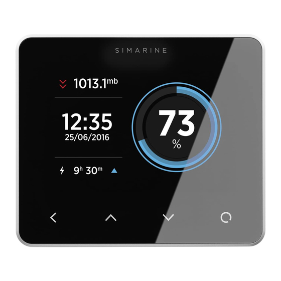
Congratulations on your purchase of the PICO Battery Monitor. Simarine developed a state of the art DC Battery monitor. PICO is a water and dust resistant device used to monitor DC power sources as batteries and solar panels. The information is displayed on a large 3,5” high resolution IPS display with Gorilla®... -
Page 9: Accessories
Accessories... - Page 10 2. Accessories PICO is compatible with the following SIMARINE modules: · SC303 Digital Shunt – 300A Shunt, for up to 75V systems. · SC503 Digital Shunt – 500A Shunt, for up to 75V systems. · SDI01 Inclinometer – High-resolution digital inclinometer for pitch and roll with manual calibration.
-
Page 11: Safety
Safety... - Page 12 3. Safety Electrical specialists with proper safety equipment should make installation of Simarine electronics. When working with batteries, you should wear protective clothing and eye protection. CAUTION: Batteries contain acid, a corrosive, colorless liquid that will burn your eyes, skin, and clothing. Should the acid come in contact with eyes, skin or clothing, wash it immediately with soap under fresh water for at least 15 minutes, and seek medical support immediately.
-
Page 13: Declaration Of Conformity
Declaration of conformity... - Page 14 MANUFACTURER: SIMARINE d.o.o. ADDRESS: Ulica škofa Maksimilijana Držecnika 6, SI-2000 Maribor, Slovenia, EU Declares that the following product: PRODUCT TYPE: PICO Conforms to the requirements of the following Directives of the European Union: EMC Directive 2014/30EU, RoHS Directive 2002/95/EC The above product conforms with the following harmonized...
-
Page 15: Installation
Installation... -
Page 16: Pico Mounting
PICO should be installed in a visible place to provide good readability. Please note that ONLY the PICO display unit is water and dust resistant! Any other modules including splitter shouldn't expose to high humidity or liquids in any case. -
Page 17: Pico Standalone
Mark mounting holes using the supplied installation template. Drill all holes. Connect the connector on the back side of PICO to the splitter cable (be sure to align the pins correctly) and fasten it by turning the safety ring clockwise. -
Page 18: Pico Panel-Mount
PICO Panel-mount PICO Panel-mount version dimensions are 108.5 x 94 x 10 mm (4.27 x 3.70 x 0.39 in). It needs an installation cutout of 98 x 83mm. It can be mounted with supplied threaded rods and brackets or bonded with adhesive if there is no rear access to the mounting surface. -
Page 19: Connecting
2 x 2 x 0.25mm2 Twisted pair (recommended) PICO connects to the SiCOM bus via attached Splitter, which is a SiCOM bus entry point for other devices and the power connection. Splitter must connect to the power source (6-35V) with the red/black cable. It is recommended to connect the power cable behind the main switch, so you can power off the complete system, although the total power consumption of the system is very low (usually <100mA at normal operation). -
Page 20: Basic Setup
Basic Setup... -
Page 21: Voltmeters
6. Basic Setup PICO’s menu management is transparent and easy to use. All changes can be done using four touch buttons below the screen. Menus and settings can differ from your device since future firmware upgrades might cause some minor changes in the menus and settings. -
Page 22: Settings Screen
6.3 Settings Screen A – Label indicates current position in the menu. B – Currently selected item. C – Arrow indicates there is at least one more menu item in the arrow direction. D – Arrow indicates there is a submenu. E –... -
Page 23: Start Screen After First Connection
6.4 Start screen after first connection After installation and first connection, you should see a screen similar to the one shown below. After the first power-on, there are no batteries and tanks. Long press button to enter the settings menu. -
Page 24: Battery Configuration
6.5 Battery configuration PICO shows all properly configured batteries. Each correctly configured battery will automatically show up on PICO. The following section describes how to set up a battery on PICO. 6.5.1 Adding a new battery In the settings menu navigate to DEVICES > BATTERY Select “Add new”... - Page 25 · AMMETERS - Select the current sensor connected to the battery. You can select only current sensors that are not already used by another battery configuration. For a battery configuration without a shunt (voltage-only), leave ammeters empty. · TEMPERATURE SENSOR- Select a temperature sensor if you have one installed and configured. ·...
-
Page 26: Advanced Settings
TTG SOC MIN – Represents a declared offset from the actual battery state. Set by default to 20% means that when PICO will display the remaining state of battery to be 0%, the actual state of the battery will be 20%. In case you want to compare PICO readings to internal battery monitoring system provided by the battery manufacturer, it is important to set this parameter to 0%, which will give you the absolute state of the battery. - Page 27 Set manually -> Use this calibrate the batteries state of charge to 100%. You should use this functionality only when the battery is actually full. Once you select this option, the PICO will note the battery as full and after that it will rely on the calculations based on the input/output current readings.
-
Page 28: Tank Configuration
· NAME - Name the tank accordingly · TYPE - Select the tank type (WATER, FUEL, WASTEWATER), which defines the color of the tank on Pico’s screen. · SENSOR TYPE - Select the used sensor's type (RESISTANCE or VOLTAGE) ·... - Page 29 For square shaped tanks we suggest two calibration points (full and empty). For irregular shaped tanks, we suggest you input a third (the middle) point. The rest will be calculated by PICO on the fly. ·...
-
Page 30: Temperature Sensor Configuration
INSTANCE – An identifier for NMEA2000 network. For use with NMEA2000 each temperature sensor has to have a unique instance field. 6.8 Inclinometer configuration PICO shows all properly configured inclinometers. Each correctly configured sensor will automatically show up on PICO. The following section describes how to set up a sensor on PICO. -
Page 31: Adding A New Inclinometer
DELETE - With this option, you can delete the selected inclinometer sensor. 6.9 User sensor configuration PICO shows all properly configured user sensors. Each correctly configured user sensor will automatically show up on PICO. The following section describes how to set up a sensor on PICO. -
Page 32: Adding A New User Sensor
6.9.1 Adding a new user sensor In the settings menu, navigate to DEVICES > USER SENSORS. Select “Add new” and fill in the requested data. · NAME – Name the user sensor. · VOLTMETER – Select the voltage input used to measure the analog output of your voltage type user sensor. ·... - Page 33 Pressing the enter button will open a settings screen for the selected sensor. NAME - Assign a display name of the current sensor. RANGE - Adjust the presentation of the current reading for the current sensor. By default the value is set 100A and it means,C that the bar used for visually representing the measured current will be displayed as full at 100A (the default range is betweenC 0A - bar empty and 100A - bar full).
- Page 34 DEVICE - Displays a full ID of the current sensor. This is read only and it will not change even if you rename the sensor. MERGE WITH - Gives you an option to merge the sensor with another sensor. That way you tell PICO to consider the...
-
Page 35: Screens
Screens... -
Page 36: Batteries Screen
Up to four tanks and four thermometers will join on a single screen. If there are more, they will divide into two or more screens. There is also a separate barograph screen on PICO. 7.1 Batteries screen Screens for showing battery data differ depending on how many current sensors are connected to a certain battery. -
Page 37: Tanks Screen
Depending on the selected tank types, they are represented with different colors. If the tank sensor isn’t selected in the tank settings or the sensor got disconnected from the PICO system, the “OFFLINE” symbol will appear on the screen. If this situation occurs, check the sensor setting of the tank. -
Page 38: Temperatures Screen
(°C or °F). If the temperature sensor is not selected in the temperature sensor settings or the sensor is disconnected from the PICO system, the “OFFLINE” symbol will appear. If this situation occurs, please check the temperature sensor setting. If a device is selected, please check if all the cables are properly connected. -
Page 39: Barograph Screen
7.4 Barograph screen The symbol on the left shows the current air pressure trend. The arrow shows trend direction (up – rising or down – falling). If the pressure is increasing or decreasing rapidly (1.0 mbar/h or more), two arrows are shown. Below the trend symbol, two values show the current trend and current sea level pressure. -
Page 40: Inclinometers Screen
7.5 Inclinometers screen If you have an inclinometer installed, the “Inclinometers screen” shows your pitch and roll data. Pitch is shown on the left side of the screen. The left side of the line represents the front of the vehicle or boat (bow), while the right side of the line represents the back of the vehicle or boat (stern). -
Page 41: User Sensors Screen
7.6 User Sensors Screen... -
Page 42: Alarms Screen
7.7 Alarms screen When an alarm is triggered it is shown on PICO (see image below). From there you can control the alarm state. Hide, which hides the alarm from the display. Snooze, for 5 or 30 minutes, which means it is hidden for 5 or 30 minutes and then displayed again if still active. The output is active (if configured). -
Page 43: Device Configuration
Device configuration... -
Page 44: General Settings
8.1.1 Screen AUTO BRIGHTNESS - When auto-brightness is enabled, Pico’s internal light sensors automatically adjust the screen brightness to match the ambient lighting conditions. BRIGHTNESS - The brightness level used during normal operation. When AUTO BRIGHTNESS is enabled, this is the maximum brightness level. -
Page 45: Device
This determines which battery will be displayed on the home screen. BATTERY - POWER MANAGEMENT --> AUTO POWER OFF - Automatically powers off the PICO, if this is ON. POWER MANAGEMENT --> AUTO POWER OFF DELAY - Automatically powers off the PICO after selected time. -
Page 46: Data Management
ALARM VALUE - a limit value which fires the alarm. · SILENT if enabled, there will be no audible signal when the alarm fires. The alarm warning will only appear on PICO’s screen. · ALARM DELAY, the time delay with which the alarm is fired. The alarm fires when only the measured value is below (for alarm low) or above (for alarm high) the “alarm value”... -
Page 47: Devices
Batteries List of batteries which you have added to your PICO. By selecting a certain battery, you can view or change its settings, and you can delete the battery if you need to. By selecting “Add new” you can add a new battery. -
Page 48: Tanks
8.3.2 Tanks List of tanks which you have added to your PICO. By selecting a certain tank, you can view or change its settings, and you can delete the tank if you need to. By selecting “Add new” you can add a new tank. -
Page 49: Inclinometer
User sensors List of custom sensor which you have added to your PICO. By selecting a certain sensor, you can view or change its settings, and you can delete the sensor if you need to. By selecting “Add new” you can add a custom user sensor. -
Page 50: Ap Mode
Example: if your PICO’s serial number is 12345678, then the default Wi-Fi SSID is pico5678 and the password is pico1234. SSID - SSID stands for Service Set Identifier. In AP Mode, it is the Wi-Fi network name that is created by PICO. TCP IP - Shows the default IP of your PICO. -
Page 51: Sta Mode
8.4.2 STA Mode When in STA mode, you can connect PICO to your local router and connect with your smartphone via a router. This mode enables more than one mobile app connecting to PICO at the same time. To set up STA mode take the following steps: ·... -
Page 52: Date And Time
In this menu, you can set the time, date, and time zone manually, but we do not recommend to do it, because these values will be overridden by your smartphone settings each time you connect the phone to your PICO and start the Simarine application*. -
Page 53: System
DEBUG SCREEN - Opens the debug menu, listing all the services and displaying whether the service is running (1) or not (0). SYSTEM RESET - Deletes all the devices from the PICO. When clicked on, it will demand a PIN code, the code 1 2 3 4 1 2, after that you can factory reset the PICO with long pressing the button. -
Page 54: Mobile Application
Mobile application... - Page 55 You can also change the PICO settings on your smartphone, and upgrade Simarine firmware to the latest version. Find your Simarine – application in your mobile store by scanning the QR code below or visiting below link for your app store.
-
Page 56: Save And Restore Settings
Save and restore settings... - Page 57 You can restore to your previously saved settings if your PICO's physical configuration has not been changed (no shunts or modules have been added or removed). If your PICO's physical configuration has changed, you will not be able to restore to the settings that had been saved before the configuration has changed.
- Page 58 Firmware upgrade...
- Page 59 2. As soon as the start-up logo appears press and hold the left arrow key until PICO enters in text-only mode. 3. Connect your smartphone to PICO via Wi-Fi. A blue line of text will appear on PICO as soon as the connection is established.
- Page 60 Technical specifications...
- Page 61 12. Technical specifications PICO BATTERY MONITOR Operating Power source voltage range 6 - 35 V Temparature range -20°C to +70°C (-4°F TO +158°F) Power consumption at 12 V Operating, WiFi On, 100% illumination 90 mA Operating, WiFi Off, 70% illumination...
- Page 62 WIFI Radio Frequency Band 2,4 GHz Monitoring capabilities Up to Batteries Shunts Temperature sensors Tank level sensors Inclinometer sensors Dimensions (without connector) PICO 157.10 x 82.10 x 5.60 mm 6.18 x 3.23 x 0.22 in...
- Page 63 Safe Voyage.
Need help?
Do you have a question about the PICO and is the answer not in the manual?
Questions and answers