Table of Contents
Advertisement
Quick Links
Advertisement
Table of Contents

Subscribe to Our Youtube Channel
Related Manuals for SIMARINE VIA


Summary of Contents for SIMARINE VIA
- Page 1 S I M A R I N E ® USER MANUAL V8.0...
- Page 2 © 2023 SIMARINE All rights reserved. No parts of this work may be reproduced in any form or by any means - graphic, electronic, or mechanical, including photocopying, recording, taping, or information storage and retrieval systems - without the written permission of the publisher.
-
Page 3: Table Of Contents
Accessories ..........................11 Safety ............................. 13 Declaration of conformity ......................15 Installation ..........................17 Basic Setup ..........................19 VIA buttons ......................................21 Settings Screen ...................................... 23 Start screen after first connection ................................ 24 Battery configuration .................................... 25 6.4.1 Adding a new battery ..................................25 6.4.2... - Page 4 Inclinometer configuration ................................... 32 6.7.1 Adding a new inclinometer ................................32 User sensor configuration ..................................33 6.8.1 Adding a user sensor ..................................33 Current sensor configuration ................................34 6.9.1 Adding a current sensor ................................. 34 Device configuration ........................ 37 General settings ..................................... 38 7.1.1 Screen ......................................
- Page 5 7.3.8 Inclinometers ....................................46 7.3.9 User Sensors ....................................47 7.3.10 Control unit ....................................47 7.3.11 Power unit ...................................... 47 WI-FI ........................................48 7.4.1 AP Mode ......................................48 7.4.2 STA Mode ....................................... 48 Date & Time ......................................50 Service ........................................51 System ........................................
-
Page 7: Introduction
Introduction... -
Page 8: About
It comes with 8 control buttons prepared for the convenience of the user. VIA is capable of monitoring up to 6 batteries, 14 tanks, 14 temperatures, and 20 independent current sensors (shunts) as well as controlling 2 relay switches. It is equipped with a Wi-Fi module to communicate with the application available for Android™... -
Page 9: Schematics
1.2 Schematics All measurements are in millimeters (mm). Required mounting space is at least 30 mm behind the casing. -
Page 11: Accessories
Accessories... - Page 12 2. Accessories VIA is compatible with the following SIMARINE modules: · SC303 Digital Shunt – 300A Shunt, for up to 75V systems. · SC503 Digital Shunt – 500A Shunt, for up to 75V systems. · SDI01 Inclinometer – High-resolution digital inclinometer for pitch and roll with manual calibration.
-
Page 13: Safety
Safety... - Page 14 3. Safety Electrical specialists with proper safety equipment should make installation of Simarine electronics. When working with batteries, you should wear protective clothing and eye protection. CAUTION: Batteries contain acid, a corrosive, colorless liquid that will burn your eyes, skin, and clothing. Should the acid come in contact with eyes, skin or clothing, wash it immediately with soap under fresh water for at least 15 minutes, and seek medical support immediately.
-
Page 15: Declaration Of Conformity
Declaration of conformity... - Page 16 4. Declaration of conformity MANUFACTURER: SIMARINE d.o.o. ADDRESS: Ulica škofa Maksimilijana Držecnika 6, SI-2000 Maribor, Slovenia, EU Declares that the following product: PRODUCT TYPE: V I A Conforms to the requirements of the following Directives of the European Union: EMC Directive 2014/30EU, RoHS Directive 2002/95/EC...
-
Page 17: Installation
Installation... - Page 18 Mark mounting holes using the supplied installation template. Drill all holes. Connect the connector on the back of the VIA to the splitter cable (be sure to align the pins correctly) and fasten it by turning the safety ring clockwise.
-
Page 19: Basic Setup
Basic Setup... - Page 20 6. Basic Setup Controlling the menus of the VIA is intuitive and easy to use. All adjustments can be performed by using the four touch buttons below the screen. Menus and settings in the picture below can differ from the menus and settings on your device since future firmware upgrades might cause some minor changes of the menus and settings.
-
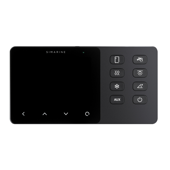
Page 21: Via Buttons
6.1 VIA buttons You can enable different devices connected to the SPDU-52 by pressing the button with the corresponding symbol on the VIA (e.g. pressing the lights button will turn on the lights). You can also switch between different screens by pressing the arrow buttons on the touch screen. - Page 22 Thermometer order, names, min. and max. ranges, and temperature units can be changed in the settings menu. · The AC button is configured on the SPDU-52 as the third button by default (K3 on the cover scheme). Pressing the button enables the AC (air conditioning).
-
Page 23: Settings Screen
6.2 Settings Screen A – Label indicates current position in the menu. B – Currently selected item. C – Arrow indicates there is at least one more menu item in the arrow direction. D – Arrow indicates there is a submenu. E –... -
Page 24: Start Screen After First Connection
6.3 Start screen after first connection After the installation and first connection, you should see a screen similar to the one shown below. After the first power-on, there are no batteries and tanks displayed. Long press the button to enter the settings menu. -
Page 25: Battery Configuration
6.4 Battery configuration The VIA shows all properly configured batteries. Each correctly configured sensor will automatically show up on the VIA. The following section describes how to set up a sensor on the VIA. 6.4.1 Adding a new battery In the settings menu navigate to DEVICES > BATTERY Select “Add new”... - Page 26 · AMMETERS - Select the current sensor connected to the battery. You can select only current sensors that are not already used by another battery configuration. For a battery configuration without a shunt (voltage-only), leave ammeters empty. · TEMPERATURE SENSOR- Select a temperature sensor if you have one installed and configured. ·...
-
Page 27: Advanced Settings
6.4.2 Advanced settings Advanced users may adjust some additional battery settings to customize the battery data display. It is not suggested to change these settings – the defaults should be suitable for all battery types. · TTG AVG – averaging interval for calculating TTG (time-to-go). “Short” means that TTG will respond to the change in current more quickly, and “Very long”... - Page 28 These settings are only relevant when the battery is monitored using a shunt (current + voltage). Here, users may set additional battery full parameters, which will be used by PICO to help determine when the battery is full. Example: - If you have a 13,8V 100Ah battery, then you can use the settings from the picture above. - System voltage (12V) x factor (1.15) = 13,8V ->...
-
Page 29: Tank Configuration
6.5 Tank configuration The VIA shows all properly configured tanks. Each correctly configured sensor will automatically show up on the VIA. The following section describes how to set up a sensor on the VIA. 6.5.1 Adding a new tank After connecting a tank sensor to an appropriate module (ST107, SC303/503, SCQ25T) input, you can configure the tank by following these steps: In the settings menu, navigate to DEVICES >... - Page 30 COMPATIBLE TANK SENSORS: Any analog voltage/resistance type tank sensor, that is made for general use and not locked to a specific tank level monitor, will work with the SIMARINE system. The compatible ranges are: Resistance: 0 Ohm - 65000 Ohm (65kOhm) or anything in between.
-
Page 31: Temperature Sensor Configuration
6.6 Temperature sensor configuration The VIA shows all properly configured temperature sensors. Each correctly configured sensor will automatically show up on the VIA. The following section describes how to set up a sensor on the VIA. 6.6.1 Add a new temperature sensor In the settings menu, navigate to DEVICES >... -
Page 32: Inclinometer Configuration
6.7 Inclinometer configuration The VIA shows all properly configured inclinometers. Each correctly configured sensor will automatically show up on the VIA. The following section describes how to set up a sensor on the VIA. 6.7.1 Adding a new inclinometer SIMARINE DIGITIAL INCLINOMETER MODULE DOES NOT REQUIRE ADDING A NEW INCLINOMETER OR INPUTTING ANY SETTINGS, AS THAT WILL BE ADDED AUTOMATICALLY WHEN SD01-DIGITAL INCLINOMETER IS CONNECTED TO THE SYSTEM (Plug&Play). -
Page 33: User Sensor Configuration
6.8 User sensor configuration The VIA shows all properly configured user sensors. Each correctly configured sensor will automatically show up on the VIA. The following section describes how to set up a sensor on the VIA. 6.8.1 Adding a user sensor In the settings menu, navigate to DEVICES >... -
Page 34: Current Sensor Configuration
6.9 Current sensor configuration The VIA shows all properly configured current sensors. Each correctly configured sensor will automatically show up on the VIA. The following section describes how to set up a sensor on the VIA. 6.9.1 Adding a current sensor List of all current sensors (shunts). - Page 35 to which this shunt is assigned to. In case there a multiple shunts in the system it is important to watch out for a possible "double current" problem (when the same current is calculated twice). This happens if the same current passes through multiple shunts. Example: a fridge is monitored individually with a dedicated current sensors, but the same current passes also through the main battery shunt.
-
Page 37: Device Configuration
Device configuration... -
Page 38: General Settings
7. Device configuration You can enter the settings menu by long pressing the button. To navigate through the list, use up and down arrow buttons. To select an item, press the enter button. To navigate one level back, use the back button. 7.1 General settings This menu offers screen, language, units, and sleep settings. -
Page 39: Device
· AUTO SLEEP - Enable/Disable auto sleep function. · Time after which the VIA goes into sleep mode if the AUTO SLEEP setting is enabled. SLEEP AFTER - · If SLEEP SCREEN is enabled the VIA will display home screen when in SLEEP MODE. -
Page 40: Data Management
7.2 Data management This menu enables you to set up alarms for certain measurements. Here, you can choose the quantity, the device, low and high values for alarm, and you can turn the high/ low-value alarms on and off. · ALARM LOW: Low-value alarm fires when the measured value is lower than the setup alarm value ·... -
Page 41: Alarm Screen
7.2.1 Alarm screen When an alarm is triggered it is shown on the VIA (see image below). From there you can control the alarm state. Hide, which hides the alarm from the display. Snooze, for 5 or 30 minutes, which means it is hidden for 5 or 30 minutes and then displayed again if still active. The output is active (if configured). -
Page 42: Devices
7.3 Devices Here you can manage all the devices connected to your VIA. When you connect a new module to your VIA system (e.g. a new shunt), some new devices will automatically appear on the device list (e.g. current sensors, voltmeters, ohmmeters, etc.). -
Page 43: Tanks
7.3.2 Tanks List of tanks you have added to your VIA. By selecting a specific tank, you can view or change its settings or delete it if necessary. By selecting “Add new”, you can add a new tank. For more information go to... -
Page 44: Temperature Sensors
Temperature sensors List of temperature sensors that you have added to your VIA. By selecting a specific sensor, you can view or change its settings or delete it if necessary. By selecting “Add new”, you can add a new temperature sensor. For more information go to... -
Page 45: Current Sensors
Current sensors List of current sensors that you have added to your VIA. By selecting a specific sensor, you can view or change its settings or delete it if necessary. By selecting “Add new”, you can add a new current sensor. For more information go to... -
Page 46: Ohmmeters
Inclinometers List of inclinometer sensors that you have added to your VIA. By selecting a specific sensor, you can view or change its settings or delete it if necessary. By selecting “Add new”, you can add a new analog sensor with voltage output. For more... -
Page 47: User Sensors
User Sensors List of custom sensors that you have added to your VIA. By selecting a specific sensor, you can view or change its settings or delete it if necessary. By selecting “Add new”, you can add a custom user sensor. For more information go to... -
Page 48: Wi-Fi
AP Mode When in AP mode, the VIA creates its wireless network. If you want to connect to it with your smartphone, please connect to the network whose name corresponds to SSID setting value. Wireless network password can be changed with PASSWORD setting. - Page 49 If the VIA can’t find your router SSID, check if SSID broadcasting is enabled on your router. The Dynamic Host Configuration Protocol (DHCP) should be enabled on the router to assign an IP address dynamically.
-
Page 50: Date & Time
DATE - Set the current date. The value is overridden each time you connect the phone to your VIA and start SIMARINE application. TIME ZONE - Set the current time zone. This value is overridden each time you connect the phone to your VIA and start SIMARINE application. -
Page 51: Service
DEBUG SCREEN - Opens the debug menu, listing all the services and displaying whether the service is running (1) or not (0). SYSTEM RESET - Deletes all the devices from the VIA. When clicked on, it will demand a PIN code, the code 1 2 3 4 1 2, after that you can factory reset the VIA with long pressing the button. -
Page 52: System
Under the SYSTEM section you can find the following information: COMMUNICATION DEVICES - List of all the devices (modules) that are connected to the VIA, together with the bus communication quality (%). SYSTEM INFO - Displays the VIA's serial number, currently installed firmware version and free memory. -
Page 53: Panel And Power Unit Configuration
Panel and Power Unit configuration... - Page 54 8. Panel and Power Unit configuration VIA supports assigning which button controls which relay. User can either configure an identifier of a specific button or an identifier of a specific relay. You can adjust the buttons on MENU > DEVICES > CONTROL UNIT > SCC8 screen.
- Page 55 INSTANCE = 7 MODE = TOGGLE SCREEN = OFF BUTTON 7 INSTANCE = 8 MODE = TOGGLE SCREEN = OFF The default mapping instance properties of the is therefore: Make sure that the same instance property is not shared by multiple buttons. You can adjust the relays (OUTPUTS) on MENU >...
- Page 56 INSTANCE = 3 STARTUP STATE = OFF OUTPUT 3 INSTANCE = 4 STARTUP STATE = OFF OUTPUT 4 INSTANCE = 5 STARTUP STATE = OFF OUTPUT 5 INSTANCE = 6 STARTUP STATE = OFF The default mapping instance properties of the outputs (RELAYS) is therefore: Make sure that the same instance property is not shared by multiple outputs (RELAYS).
-
Page 57: Configuring A Button To Display A Specific Screen
8.1 Configuring a button to display a specific screen You can configure a button so that a specific monitoring screen will be display when the button is pressed. The following configurations displays an inclinometer screen when the user presses the button 6 (7). Navigate to MENU >... - Page 58 INSTANCE = 1 MODE = TOGGLE SCREEN = OFF BUTTON 1 INSTANCE = 2 MODE = TOGGLE SCREEN = OFF Here you can swap the functions of these two buttons by swapping the INSTANCE field: BUTTON 0 INSTANCE = 2 MODE = TOGGLE SCREEN = OFF BUTTON 1...
-
Page 59: Mobile App
Mobile App... - Page 60 You can also change the VIA settings on your smartphone, and upgrade Simarine firmware to the latest version. Find your Simarine – application in your mobile store by scanning the QR code below or visiting below link for your app store.
-
Page 61: Save And Restore Settings
Save and restore settings... - Page 62 You can restore to your previously saved settings if your VIA's physical configuration has not been changed (no shunts or modules have been added or removed). If your VIA's physical configuration has changed, you will not be able to restore to the settings that had been saved before the configuration has changed Before executing SYSTEM RESTORE make sure you do a SYSTEM RESET - which will erase any existing configurations.
-
Page 63: Firmware Upgrade
Firmware upgrade... - Page 64 2. As soon as the start-up logo appears press and hold the left arrow key until VIA enters in text-only mode. 3. Connect your smartphone to VIA through Wi-Fi. A blue line of text will appear on VIA as soon as the connection is established.
-
Page 65: Technical Specifications
Technical specifications... - Page 66 12. Technical specifications Operating Voltage range 6 - 22V Temperature range -20°C – 70°C (-4°F – 158°F) Power consumption at 12V Operating, Wi-Fi on, 100% illumination 100mA Operating, Wi-Fi off, 70% illumination 40mA Stand by, Wi-Fi off, 0% illumination 22mA Power off, Logger still active Display capabilities Current...
- Page 67 Resolution 0,001 V Amp hours (Ah) ±0,1 Ah Temperature Range -40°C to + 150°C Resolution 0,1 °C / °F SOC - State of charge 0 - 100% WiFi Radio frequency bands 2.4GHz Dimensions (without connector) 157.10 x 82.10 x 5.60mm 6.18 x 3.23 x 0.22in Connectivity Up to...
- Page 68 Tank level sensors Inclinometer sensors...
- Page 69 Safe Voyage.
Need help?
Do you have a question about the VIA and is the answer not in the manual?
Questions and answers