Table of Contents

Related Manuals for SIMARINE PICO


Summary of Contents for SIMARINE PICO
- Page 1 PICO and PICOone Battery and Tank Monitoring System USER MANUALS Revision 1.3 SIMARINE d.o.o. | Ulica skofa Maksimilijana Drzecnika 6 | SI - 2000 Maribor | Slovenia | EU www.simarine.net | Copyright © 2017 SIMARINE d.o.o. | All Rights Reserved.
-
Page 2: Table Of Contents
Table of contents Introduction ...................... 6 Accessories ...................... 6 Safety ....................... 6 Declaration of conformity ................7 Installation ....................... 7 PICO mounting ..................7 PICO standalone ..................8 PICO panel-mount .................. 9 Connecting .................... 11 5.4.1 Power cable ..................11 5.4.2... - Page 3 NAME ..................23 8.3.1.2 TYPE ..................23 8.3.1.3 CAPACITY ................23 8.3.1.4 VOLTMETER ................. 23 8.3.1.5 AMMETERS ................24 8.3.1.6 TEMPERATURE SENSORS ..........24 8.3.2 TANKS ..................... 24 8.3.2.1 NAME ..................24 8.3.2.2 TYPE ..................24 8.3.2.3 SENSOR TYPE ............... 25 PICO...
- Page 4 ADD CURRENT ..............28 8.3.4.5 BATTERY ................29 8.3.4.6 DISPLAY PRIORITY ............. 29 8.3.5 VOLTMETERS ................30 8.3.6 OHMMETERS ................. 30 8.3.7 COULOMB COUNTER..............30 WI-FI..................... 31 8.4.1 OPERATION ..................31 8.4.2 AUTO OFF ..................31 8.4.3 MODE ....................31 PICO...
- Page 5 8.6.1 ALTITUDE ..................33 8.6.2 TIME INTERVAL ................33 SYSTEM ....................33 8.7.1 COMMUNICATION DEVICES ............33 8.7.2 SYSTEM INFO ................34 8.7.3 SYSTEM RESET ................34 Mobile App ....................34 Firmware Upgrade ..................35 Technical Specifications ................36 PICO...
-
Page 6: Introduction
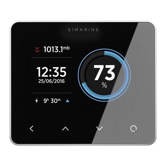
IPS display with Gorilla Glass and anti-reflective coating to ensure superior visibility. PICO is capable of monitoring up to 6 batteries, 14 tanks, 14 temperatures and 20 independent current sensors (Shunts). PICOone is capable of monitoring up to 2 batteries, 2 tanks, 2 temperatures and 20 independent current sensors (Shunts). -
Page 7: Declaration Of Conformity
Installation 5.1 PICO mounting SIMARINE PICO should be installed in a visible place to provide good readability. Please note that ONLY the PICO/PICOone display unit is water and dust resistant! Any other modules including splitter should not be exposed to... -
Page 8: Pico Standalone
The mounting process requires drilling of 5 (PICOone) or 6 (PICO) mounting holes and access to the rear of the mounting surface. In case you have NO rear access, you can bond it using supplied double sided tape. -
Page 9: Pico Panel-Mount
Mark the cutout line with the supplied installation template. Using a saw, carefully cut out the marked area. Connect the connector on the back side of PICO to the splitter cable (be sure to align the pins correctly) and fasten it by turning the safety ring clockwise. - Page 10 10,00 Unit: mm 108,50 Waterproof air pressure vent WARRANTY VOID IF SEAL BROKEN! 11,00 96,50 6,00 PICO...
-
Page 11: Connecting
2x2x0.25 mm2 Twisted pair (recommended) Pico is connected to the SiCOM bus via attached Splitter, which is an entry point for other devices and for the power connection. Splitter must be connected to the power (6-35V) with red/black cable. It is recommended that the power cable is connected behind the main switch, so you can power off the complete system, although the total power consumption of the system is very low (usually <100mA... -
Page 12: How To Connect A Sc300/Sc302T/Sc500 Shunt
How to connect a SCQ25 Quadro Digital Shunt module You can find the latest SCQ25 QUADRO DIGITAL SHUNT MODULE on this link (or visit our website: https://www.simarine.net). 5.4.5 How to connect a Shunt SCQ25T Quadro Digital Shunt ant Tank module... -
Page 13: Basic Setup
6 Basic setup PICO’s menu management is transparent and easy to use. All changes can be done using four touch buttons below the screen. Menus and settings on the picture below can differ from the menus and settings on your device, since future firmware upgrades might cause some minor changes in the menus and settings. -
Page 14: Start Screen After First Connection
After installation and first connection you should see a screen similar to the one shown below. After the first power-on there are no batteries and tanks defined and Pico only shows a barograph screen. Please long press button to enter the settings menu. -
Page 15: Battery Configuration
6.4 Battery configuration PICO shows all properly configured batteries. Each correctly configured battery will automatically show up on PICO. The following section describes how to set up a battery on PICO. 6.4.1 Add new battery The following steps are equal for SC300, SC302T and SC500 digital shunts. -
Page 16: Tank Configuration
• Confirm and save the battery configuration with button. The newly added battery should now be visible on one of the PICO’s screens once you exit the settings menu. 6.5 Tank configuration PICO shows all properly configured Tanks. Each configured Tank will automatically show up on PICO. -
Page 17: Displaying Battery, Tank, Temperature And Air Pressure Measurements
(resistance or voltage) must be selected. • Confirm and save the tank configuration with button. The newly added tank should now be visible on one of the PICO’s screens once you exit the settings menu. 7 Displaying battery, tank, temperature and air pressure measurements You can switch between different screens by pressing the up and down arrow buttons. -
Page 18: Batteries Screen
(amps) is also shown on the battery page. Pico's algorithm for calculating state-of-charge (SOC) is not a simple Ah- counter. It is constantly monitoring battery current, voltage and temperature. These data are compared to the internal battery model and its parameters are constantly being adjusted so that the model fits to the actual data. -
Page 19: Temperatures Screen
If the tank sensor is not selected in the tank settings or the sensor is disconnected from the PICO system, the “OFFLINE” symbol will appear on the screen. If this situation occurs, please check the sensor setting of the tank. If sensor is selected, please check if all the cables are properly connected. -
Page 20: Device Configuration
BRIGHTNESS is enabled, this is the maximum brightness level. 8.1.1.3 MIN. BRIGHTNESS Min. brightness has two functions. When PICO is in sleep mode the illumination is set to min. brightness level. When AUTO BRIGHTNESS is enabled, it defines the minimum illumination. -
Page 21: Device
If enabled, PICO goes into standby mode after STANDBY AFTER time. 8.1.2.2 STANDBY AFTER Time after which the PICO goes into sleep mode if AUTO STANDBY setting is enabled. 8.1.2.3 SLEEP SCREEN If SLEEP SCREEN is enabled, PICO will show sleep screen if it is in standby mode. PICO... -
Page 22: Language
The alarm warning will only appear on PICO’s screen. 8.3 DEVICES Here, you can manage all the devices that are connected to your PICO. When you connect a new module to your PICO system (e.g. a new shunt), some new devices will automatically appear on the devices list (e.g. -
Page 23: Batteries
8.3.1 BATTERIES This is the list of the batteries which you have added to your PICO. By selecting a certain battery, you can view or change its settings, and you can delete the battery if you need to. By selecting “Add new”, you can add a new battery. -
Page 24: Ammeters
8.3.2 TANKS This is the list of the tanks which you have added to your PICO. By selecting a certain tank, you can view or change its settings, and you can delete the tank if you need to. By selecting “Add new”, you can add a new tank. -
Page 25: Sensor Type
If you are adding a new tank, at least two calibration points have to be added for a proper configuration. More calibration points will enable PICO to show tank level more accurately. Up to 11 calibration points can be added. -
Page 26: Delete
8.3.3 TEMPERATURE SENSORS This is the list of the temperature sensors which you have added to your PICO. By selecting a certain sensor, you can view or change its settings, and you can delete it if you need to. By selecting “Add new”, you can add a new temperature sensor. -
Page 27: Device
This setting enables you to choose between the following display priorities: HIGH, MEDIUM, LOW and HIDE. The display priority is used for ordering the thermometers on PICO’s screen. When thermometers are shown on the screen, those with HIGH display priority are shown first (leftmost), followed by thermometers with MEDIUM display priority. -
Page 28: Current Sensors
8.3.4.3 REVERSE CURRENT If you swap the wires on the shunts terminals, PICO will show the opposite value of the current. E.g. when discharging, PICO will show charge current and vice- versa. In such situation, you can use this setting to reverse the current value. If you set this value to ON, PICO will reverse the measured value. -
Page 29: Battery
This setting enables you to choose between the following display priorities: HIGH, MEDIUM, LOW and HIDE. The display priority is used for ordering the current sensors on PICO’s screen. When current sensors are shown on the screen, those with HIGH display priority are shown first (at the top), followed by sensors with MEDIUM display priority. -
Page 30: Voltmeters
8.3.5 VOLTMETERS List of all voltmeter sensors connected to PICO. Connected voltmeters are added to the list automatically. You cannot manually add a new voltmeter. In this list, you can view current readings (voltages) for all connected voltmeters. 8.3.6 OHMMETERS List of all ohmmeters connected to PICO. -
Page 31: Wi-Fi
MODE Currently, only AP mode is supported. When in AP mode, PICO creates its own wireless network. If you want to connect to PICO with your smart phone, please connect to the network whose name corresponds to SSID setting value. Wireless network password can be changed with PASSWORD setting. -
Page 32: Tcp Ip
You can find the serial number on the sticker on the back side of PICO or in the menu under SYSTEM SYSTEM INFO. This is default SSID and you can change it. 8.4.5 TCP IP Shows the default IP of PICO. -
Page 33: Time
The time interval is the default interval used when plotting the graph of pressure (barograph). 8.7 SYSTEM 8.7.1 COMMUNICATION DEVICES List of all the devices (modules) that are connected to the Pico, together with the bus communication quality (%). PICO... -
Page 34: System Info
You can also change PICO’s setting on your smart phone, and easily upgrade PICO’s firmware to a new version when it becomes available. Find your PICO – Battery Monitor app in your mobile store by scanning the QR code below or visiting below link for your app store. -
Page 35: Firmware Upgrade
10 Firmware Upgrade To ensure the best PICO experience it is recommended to upgrade PICO’s firmware to the latest version. You can do this via PICO – Battery Monitor smartphone application available on your smartphone application market as described in the previous chapter 9 Mobile App. -
Page 36: Technical Specifications
98 x 84 x 10 mm 3.85 x 3.30 x 0.39 in Panel 108.5 x 94 x 10 mm 4.27 x 3.70 x 0.39 in Connectivity Up to Batteries Shunts Temperature sensors Tank level sensors Smart phone application Logger capacity up to 3 months PICO... - Page 37 12 APPENDIX 12.1 SC500 PICO...
- Page 38 12.2 2x SC500 PICO...
- Page 39 12.3 SC500 AND ST107 PICO...
- Page 40 12.4 ST107 PICO...
- Page 41 12.5 SCQ25C PICO...
Need help?
Do you have a question about the PICO and is the answer not in the manual?
Questions and answers