Table of Contents
Advertisement
Quick Links
Content:
Introduction ........................................................................................................... 3
Product description .......................................................................................... 3
Glossary of terminology .................................................................................... 3
Connecting the control panel ................................................................................... 4
Power source and power modes ........................................................................ 4
Simarine devices .............................................................................................. 5
Sensors ........................................................................................................... 5
Connecting and switching a bilge pump ............................................................. 7
Bilge pump status indicator ............................................................................... 8
Connecting and switching remote switches ........................................................ 9
Connectors - detailed description ..................................................................... 12
CAN and NMEA ports ............................................................................................. 13
Basic description and connecting ...................................................................... 13
NMEA2000 data streaming ............................................................................... 13
NMEA2000 remote switching ............................................................................ 14
DC distribution unit ................................................................................................ 16
Table of connector pins and corresponding fuses ............................................... 17
Using the control panel and distribution units ........................................................... 20
Button illumination and errors .......................................................................... 20
Manual switching of relays on the distribution unit ............................................. 21
Predefined configurations ....................................................................................... 22
Sailboat small configuration ............................................................................. 22
Sailboat big configuration ................................................................................ 23
Motorboat configuration .................................................................................. 23
Dimensions and mounting details ............................................................................ 24
SCP-210 dimensions ........................................................................................ 24
SCP-210 cut-out template ................................................................................ 25
SPU-303 dimensions........................................................................................ 26
Change notes ........................................................................................................ 27
1
document v1.4
v1.4, 12
th
May 2023
Advertisement
Table of Contents

Subscribe to Our Youtube Channel
Related Manuals for SIMARINE Nereide 2


Summary of Contents for SIMARINE Nereide 2
-
Page 1: Table Of Contents
Product description ..................3 Glossary of terminology ..................3 Connecting the control panel ................... 4 Power source and power modes ................ 4 Simarine devices ....................5 Sensors ......................5 Connecting and switching a bilge pump ............. 7 Bilge pump status indicator ................8 Connecting and switching remote switches ............ - Page 2 v1.4, 12 May 2023...
-
Page 3: Introduction
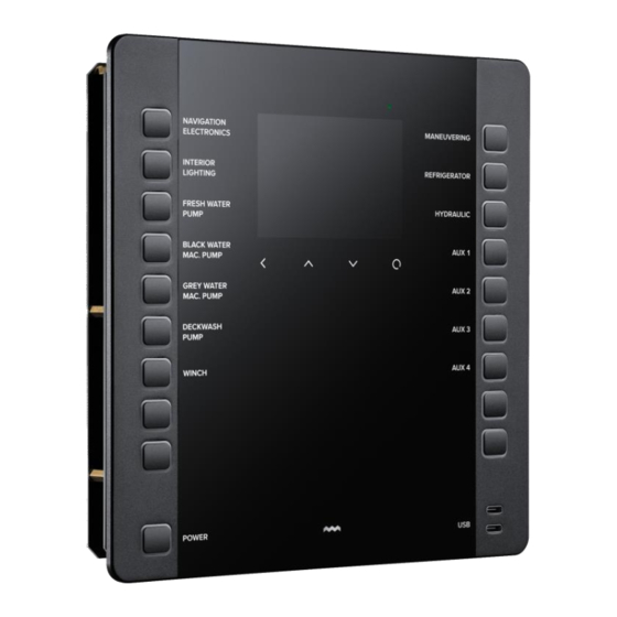
Introduction Product description SCP-210 control panel and SPU-303 DC distribution unit are Simarine products used for switching of low voltage DC consumers and devices. The panel and unit are used in conjunction. The buttons on the control panel control the states of the relays on the distribution unit. -
Page 4: Connecting The Control Panel
Connecting the control panel The control panel allows connection of up to 8 resistance sensors and 7 voltage sensors. It is also compatible with all other Simarine devices. Power source and power modes The panel requires 12 V DC voltage source protected with a 2 A fuse. Maximum ratings for the power supply voltage source are: o min.: 6 V DC... -
Page 5: Simarine Devices
Figure 2: Low power mode enable/disable switch. Simarine devices The panel supports all other Simarine devices. It connects to them through SiCOM. The devices can connect directly to the 2 SiCOM ports. The panel itself provides the power to the SiCOM ports. - Page 6 Figure 3: Control panel connections diagram. v1.4, 12 May 2023...
-
Page 7: Connecting And Switching A Bilge Pump
Connecting and switching a bilge pump Note: This function is only available per request when ordering the Nereide 2 system! A bilge pump can be connected to the control panel. The recommended wiring schematics is shown on the figure below. The +12V pin is an input for the battery voltage, and the MANUAL and AUTO pins are outputs. -
Page 8: Bilge Pump Status Indicator
Bilge pump status indicator There is also a feedback system implemented for alerting the user the status of the bilge pump connections. The status is indicated by the dedicated button showing different colours and/or flashing. The control panel monitors the input voltage on the +12V pin and the voltage on the MANUAL pin. -
Page 9: Connecting And Switching Remote Switches
Connecting and switching remote switches Note: This function is only available per request when ordering the Nereide 2 system! Up to three remote switches can be connected to the control panel. Supported remote switches can have two types of signals for controlling. A “TOGGLE” and “SWITCH” type. - Page 10 Figure 8: Toggle signal type of remote switch. Figure 9: Switch signal type of remote switch. v1.4, 12 May 2023...
- Page 11 Figure 10: Feedback signal from remote switch output. Remote switch connector pin descriptions: Voltage source input, 12V DC from battery, protected by a fuse +12V Input (recommended 1A or lookup into remote switch datasheet). If selected “SWITCH” type: constantly outputs 12V when the dedicated button is turned OFF.
-
Page 12: Connectors - Detailed Description
Connectors – detailed description Below are descriptions of connectors used to connect to the control panel (cable side). Ohmmeter inputs (resistance sensors) plug - molex 39013022 pins – molex 39000038 Voltmeter inputs: 8 pin female Wago 769-108 Power input: 3 pin female Wago 769-103 SiCAN/NMEA: DeviceNet 5 pin M12 female Remote switch:... -
Page 13: Can And Nmea Ports
CAN and NMEA ports Basic description and connecting The panel connects to the distribution unit by using a proprietary CAN bus based protocol called SiCAN. This bus uses DeviceNet 5-pin cables and T-splitters. This is the same cable as NMEA2000 drop cable. SiCAN bus is used to connect the panel and distribution unit, which requires at least 1 terminator for short connections (less than 3 meters) or 2 terminators at each end for longer connections (more than 3 meters). -
Page 14: Nmea2000 Remote Switching
SN01 NMEA2000 gateway connected to a standalone PICO. For more information look into SN01 user manual (simarine.net) NMEA2000 remote switching Note: This function is only available per request when ordering the Nereide 2 system! In addition to transmitting data from the PICO, the NMEA2000 port allows the control panel to receive switching commands. - Page 15 Figure 12: NMEA2000 switch bank indexes. v1.4, 12 May 2023...
-
Page 16: Dc Distribution Unit
DC distribution unit The DC distribution unit (SPU-303) connects to the battery through the main switch with a recommended 200 A fuse. The unit has 31 switch channels (relays) each connected to 1 or more output pins. Each relay has a corresponding fuse with a rating that must be the same or lower as the maximum allowed current through the relay. -
Page 17: Table Of Connector Pins And Corresponding Fuses
Table of connector pins and corresponding fuses Below is a table of connectors with associated relays, fuses and output pins. v1.4, 12 May 2023... - Page 18 Table 4: DC distribution unit output layout. v1.4, 12 May 2023...
- Page 19 Figure 14: Relays with corresponding pins. v1.4, 12 May 2023...
-
Page 20: Using The Control Panel And Distribution Units
Using the control panel and distribution units The control panel turns on by pressing the power button. To turn the panel off the power button should be held for 1 second. When the panel turns off it first turns off all the relays on the connected DC distribution unit. -
Page 21: Manual Switching Of Relays On The Distribution Unit
Manual switching of relays on the distribution unit In case of an error of the relay being in the wrong physical set state, the control panel will periodically command it to switch to the proper set state. While the relays on the distribution unit can be manually switched, if a user switches them while the control panel is still turned on the control panel will command the relay to the set state of the button within a few seconds. -
Page 22: Predefined Configurations
Predefined configurations Simarine currently offers 3 predefined button configurations. A configuration is a definition of which button switches which relay on the distribution unit and the label next to the button. If a customer needs a custom configuration a form to fill out can be requested from sales@simarine.net... -
Page 23: Sailboat Big Configuration
Sailboat big configuration Figure 17: SAILBOAT BIG Motorboat configuration Figure 18: MOTORBOAT v1.4, 12 May 2023... -
Page 24: Dimensions And Mounting Details
In short, the minimum distance from the mounting surface to the back of the mounting space is 74 mm. Bolts for installation are provided with all Nereide 2 control panels (4 pieces M3 bolts with easy-installation knurled nuts). v1.4, 12... -
Page 25: Scp-210 Cut-Out Template
SCP-210 cut-out template v1.4, 12 May 2023... -
Page 26: Spu-303 Dimensions
SPU-303 dimensions The dimensions for the distribution unit are provided below. Notice the distances for the mounting screws (396,50 mm x 121,00 mm). The installation screws are provided with every SPU-303 distribution unit (4 pieces truss head 3,45x12 mm self-tapping screw). Figure 20: SPU303 DC Distribution Unit general dimensions. -
Page 27: Change Notes
Added ohmmeter and voltmeter specification. Removed bilge pump and remote switch option descriptions, since the feature is not yet in production. Updated fonts and added Simarine logo in header. o Document v1.2 – 19 December 2022: Added glossary of terminology and changed 1 chapter to “Introduction”.
Need help?
Do you have a question about the Nereide 2 and is the answer not in the manual?
Questions and answers