Table of Contents
Advertisement
Quick Links
Advertisement
Table of Contents

Related Manuals for Crossfire TRION 210


Summary of Contents for Crossfire TRION 210
- Page 1 TRION 210 OWNER’S MANUAL WARNING: Read carefully and understand all ASSEMBLY AND OPERATION INSTRUCTIONS before operating. Failure to follow the safety rules and other basic safety precautions may result in serious personal injury. Revision 2018-1-31...
- Page 2 “Danger” indicates an imminently hazardous situation which, if not avoided, “Warning!” indicates a possible hazardous situation which, if not avoided, could “Caution” indicates a possible hazardous situation which, if not avoided, may “Note!” indicates a situation which implies a risk of impaired welding result and damage to the equipment.
- Page 3 fl AC welder with reduced open-load voltage. fi - IT and telecoms equipment - IT and telecoms equipment -Mains supply flame-resistant material (leather fl arc nor expose themselves to the arc rays or to hot spatter or material. your health.
- Page 4 fi supplied respirator. confi fi fi to prevent hazardous situations. fire hazards or overheat. fl position or in confined places. when in a welding area. fire. Remove fi Do not weld where fl fl atmosphere may contain fl gasoline). fl Keep a fi...
- Page 5 fi flame. gas cylinder. fittings condition. fi good condition. cylinder valve outlet. Hot parts can burn. Flying metal or dirt can injure eyes. When welding, chipping, wire flying metal. It can hurt your eyes. Noise can damage hearing. Noise can be from some working equipments or Moving parts can injure.
- Page 6 duty cycle to use the machine. Allow cooling period. flow to unit. fi fication.
- Page 7 è é é î î peut entraî Indique une situation qui implique un risque de perte de fi fi ûlures graves. Lorsque la machine est fi î î fil et fil de soudure sont fi É fi Connectez le câ maintenance.
- Page 8 fil) semi- ûr Alimentation secteur Câ Connectez le câ â â Blindage û ûler les yeux et la peau. fl non infl La soudure peut produire...
- Page 9 Travailler dans un espace confi fi fi ûr. Les étincelles de soudure et de coupe peuvent provoquer un incendie ou une explosion. Lors de la soudure, assurez-vous que le circuit de Assurez-vous que la zone est sûre avant toute soudure. Connectez le câ...
- Page 10 É fisant de personnes pour fixant sur un Gardez une distance sû toute autre source de chaleur flammes. â ç çus û avec la main nue ou la peau. ûlures. fi soudure.
- Page 11 înement. fi î utiliser la machine. mise en œuvre pour la certifi normes pour le Canada et les É...
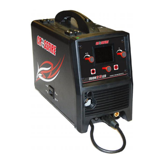
- Page 12 Please retain instructions for future reference. MIG WELDER Description The TRION 210 is a multi-process DC inverter welder, with LCD screen. This unit uses 1~Phase 120V or 230V, 50/60HZ AC power. A 15 amp time delay fuse or circuit breaker is recommended.
- Page 13 MIG/MMA WELDER Operating Instructions and Parts Manual 1.3 After unpacking unit, inspect carefully for any damage that may have occurred during transit. Check for loose, missing, or damaged parts. Shipping damage claim must be filed with carrier. Operating Instructions and Parts Manual Specifications and Dimension Description Specification...
-
Page 14: Know Your Welder
MIG/MMA WELDER Operating Instructions and Parts Manual Removing from carton 1.1 Remove cartons, bags or Styrofoam containing the welder and accessories. 1.2 Check the contents with the packing list below. Factory standard:EN60974-1 Optional accessories:Protective mask、tip、welding wire Know your Welder Front Ctrl Panel MIG Socket Torch Polarity Change Cable... - Page 15 MIG/MMA WELDER Operating Instructions and Parts Manual INPUT POWER CORD The power cord connects the welder to the 120V/230 volt power supply. 14 amp receptacle to supply power to the welder. Torch Polarity Change Cable To change the polarity of gun for kinds of core wire welding. NAMEPALTE OF WELDER The nameplate indicate the main electrical data of welder.
- Page 16 MIG/MMA WELDER Operating Instructions and Parts Manual Interface description 1. Multi-functions selection: Total 9 functions, 8 welding functions and 1 setting. Adjusting multi-function knob for selecting, press for confirming 2. Output setup: Shows output connection under different welding mode, press multi-function knob for confirming 3.
- Page 17 MIG/MMA WELDER Operating Instructions and Parts Manual 4. Material thickness: Adjusting multi-function knob to select different material thickness, press for confirming 5. Welding display:Shows all selected parameters. a. Under MIG welding, user can set wire feeding speed and voltage. Adjusting Multi-function knob to set electro-inductance, press the knob to progress basic parameter setting.
- Page 18 MIG/MMA WELDER Operating Instructions and Parts Manual c. Under Stick welding, user can set current, arc force parameter and hot start. 6. Setting interface: It shows language setting, units setting, light setting, information and recover setting. 7. Alarm interface:It shows the machine is overloaded and the internal temperature is too high.
-
Page 19: Installation
MIG/MMA WELDER Operating Instructions and Parts Manual Installation Outside Connection of the Machine 1. Power requirement AC single phase 230V or 120V , 50/60HZ fused with a 15 amp time delayed fuse or circuit breaker is required. •High voltage danger from power source! Consult a qualified electrician for proper installation of receptacle. - Page 20 MIG/MMA WELDER Operating Instructions and Parts Manual drop they produce. This drop in voltage can affect the performance of the welder. If you need to use an extension cord it must be a #12 gauge cord at the smallest. -Do not use an extension cord over 25 ft. in length. 3.
-
Page 21: Ground Clamp Connection
MIG/MMA WELDER Operating Instructions and Parts Manual 4. Ground clamp connection Clear any dirt, rust, scale, oil or paint on the ground clamp. Make certain you have a good solid ground connection. A poor connection at the ground clamp will waste power and heat. - Page 22 MIG/MMA WELDER Operating Instructions and Parts Manual -Do not touch cylinder with MIG gun. -Do not weld on the cylinder. -Always secure cylinder upright to a cart or stationary object. -Keep cylinders away from welding or electrical circuits. -Use the proper regulators, gas hose and fittings for the specific application. When MIG (solid) wires are used, the shielding gas is required.
- Page 23 MIG/MMA WELDER Operating Instructions and Parts Manual 6.2.The gas hose, regulator and gas cylinder connection Attach one end of the gas hose to the gas solenoid valve (gas inlet) located on the back panel of the welder. Attach the other end to the gas regulator which is attached to the shielding gas cylinder.
- Page 24 MIG/MMA WELDER Operating Instructions and Parts Manual 7 Installation of Wire Spool 7.1 Open the turning plate of the machine, rotate the adjusting nut on the wire shaft anti- clockwise to remove it from the wire spool screw, and then take down the wire spool block seat;...
- Page 25 MIG/MMA WELDER Operating Instructions and Parts Manual Installation of wire feeder and connection of welding stick 8.1 While installing the wire spool, check previously that wire feeding roller in the wire feeder is suitable for the contact tip in the torch and wire diameter 8.2 After the confirmation or the replacement of the wire feeding roller and contact tip, put the press roller adjusting to the machine behind.
-
Page 26: Operation
MIG/MMA WELDER Operating Instructions and Parts Manual 9.4 after the installation of wire roller, screw the cover clockwise tightly. Make sure the screw thread connection is correct, to avoid damaging of the screw thread due to the connection deviation. Remark: he spec marked on the front of the roller is the size of roller groove in the back of the roller. - Page 27 MIG/MMA WELDER Operating Instructions and Parts Manual 3.1. Angle A can be varied, but in most cases the optimum angle will be 60 degrees, the point at which the torch handle is parallel to the work piece. If angle A is increased, penetration will increase.
-
Page 28: Welding Techniques
MIG/MMA WELDER Operating Instructions and Parts Manual 5.4. With your free hand, turn the Wire Speed Dial to maximum and continue to hold onto the knob. 5.5. Lower your welding helmet and pull the trigger on the torch to start an arc, then begin to drag the torch toward you while simultaneously turning the Wire Speed Dial counter- clockwise. - Page 29 MIG/MMA WELDER Operating Instructions and Parts Manual The STRINGER BEAD Is formed by traveling with the torch in a straight line while keeping the wire and nozzle centered over the weld joint (See following figure) The WEAVE BEAD Is used when you want to deposit metal over a wider space than would be possible with a stringer bead.
- Page 30 MIG/MMA WELDER Operating Instructions and Parts Manual puddle control and allow slower rates of travel speed to achieve deeper penetration. When vertical welding, angle B (see HOLDING THE TORCH) is usually always kept at zero, but angle A will generally range from 45 to 60 degrees to provide better puddle control. OVERHEAD POSITION Is the most difficult welding position.
- Page 31 MIG/MMA WELDER Operating Instructions and Parts Manual Fillet Weld Joints. Most fillet weld joints, on metals of moderate to heavy thickness, will require multiple pass welds to produce strong joint. The illustrations in Figure 19 show the sequence of laying multiple pass beads into a T fillet joint and a lap fillet joint. 6.5 Spot welding There are three methods of spot welding: Burn-Through, Punch and Fill, and Lap.
- Page 32 MIG/MMA WELDER Operating Instructions and Parts Manual 6.6 SPOT WELDING INSTRUCTIONS 1. Select the wire diameter and heat setting recommended above for the method of spot welding you intend to use. 2. Tune in the wire speed as if you were going to make a continuous weld. 3.
- Page 33 MIG/MMA WELDER Operating Instructions and Parts Manual a. The bead will be high and irregular b. The arc will be difficult to maintain 3. When the rod is too large a. The arc will burn through light metals b. The bead will undercut the work c.
- Page 34 MIG/MMA WELDER Operating Instructions and Parts Manual 2.2 Striking the arc EXPOSURE TO A WELDING ARC IS EXTREMELY HARMFUL TO THE EYES AND SKIN. •Never strike an arc or begin welding until you have adequate protection. • Wear flameproof welding gloves, heavy long-sleeved shirt, cuffless trousers, high-topped shoes and a welding helmet or shield.
-
Page 35: Welding Position
MIG/MMA WELDER Operating Instructions and Parts Manual 2.3 Types of weld bead The following paragraphs discuss the most commonly used arc welding beads. The stringer bead Formed by traveling with the electrode in a straight line while keeping it centered over the weld joint. The weave bead Used when you want to deposit metal over a wider space than would be possible with a stringer bead. - Page 36 MIG/MMA WELDER Operating Instructions and Parts Manual The horizontal positionis is performed very much the same as the flat weld except that the angle is different such that the electrode, and therefore the arc force, is directed more toward the metal above the weld joint. This more direct angle helps prevent the weld puddle from running downward while still allowing slow enough travel speed to achieve good penetration.
- Page 37 MIG/MMA WELDER Operating Instructions and Parts Manual A solid weld bead requires that the electrode be moved slowly and steadily along the weld seam. Moving the electrode rapidly or erratically will prevent proper fusion or create a lumpy, uneven bead. To prevent ELECTRIC SHOCK, do not perform any welding while standing, kneeling, or lying directly on the grounded work.
- Page 38 MIG/MMA WELDER Operating Instructions and Parts Manual Striking the arc method following step: A.Turns on the welding torch built-in air valve Approaches the striking the arc spot the spray nozzle to cause the tungstic electrode and the work piece is separated 2~3mm B.Slowly lifts the welding torch to cause the tungstic electrode contact work piece C.Lifts the welding torch to the normal position, starts to weld...
-
Page 39: Troubleshooting Chart
MIG/MMA WELDER Operating Instructions and Parts Manual Trouble shooting Chart Breakdown Analysis Solutions Voltage is too high Switch off power source; Check (≥15%) the main supply; Restart welder when power recovers to normal Voltage is too low state. (≤15%) Bad power Improve the ventilation condition. - Page 40 MIG/MMA WELDER Operating Instructions and Parts Manual Too large contact tip Change the proper contact tip or makes the current roller unsteady Too thin power cable Change the power cable Arc is not makes the power stable and splash is astaticism large Too low input voltage...
- Page 41 MIG/MMA WELDER Operating Instructions and Parts Manual Main Circuit chart + 15V -15V IF B G N D...
-
Page 42: Spare Part List
MIG/MMA WELDER Operating Instructions and Parts Manual Spare Part List Repair Parts List 20050080074 20050170009 11010010671 11010050331 12010031515 20030320097 20040300007 20070550009 20070800015 20070890052 20020020037 11050020695 11020010571 Fixed plate of mainboard 20050050542 11050020953... - Page 43 MIG/MMA WELDER Operating Instructions and Parts Manual 11010040925 20050050408 20070570185 20070540013 12070030151 20070110022 11050070213 11050070213 11020014212 Fixed plate of wire feeder 11020014211 20200400138 20070400137 12020160812 11020014210 20080070004...
- Page 44 MIG/MMA WELDER Code. Description Specification 20200010165 Nozzle Self-protection 20200010224 Nozzle Insulation 20200010153 Contact Tip 0.023 20200010142 Contact Tip 0.03 20200010144 Contact Tip 0.035 20200010623 Diffuser 20200120069 Swanneck 20200010628 Lock Net&Front Gun Shell Trigger 20400080441 Cable 20300020163 20200010626 Spring 20200010622 M4*16 Back Gun Shell&Screw 11.8*1.8 20200010627...
- Page 45 6. Voiding Warranty subject to the terms and conditions listed below. This The limited warranty is void if the Crossfire product has Limited Warranty is for new equipment sold after the been repaired, changed, or modified by anyone other then...
Need help?
Do you have a question about the TRION 210 and is the answer not in the manual?
Questions and answers