Table of Contents

Related Manuals for Crossfire MS 210Si


Summary of Contents for Crossfire MS 210Si
- Page 1 MS 210Si OWNER’S MANUAL WARNING: Read carefully and understand all ASSEMBLY AND OPERATION INSTRUCTIONS before operating. Failure to follow the safety rules and other basic safety precautions may result in serious personal injury.
-
Page 2: Warranty
WARRANTY EFFECTIVE JULY 1, 2015 LIMITED WARRANTY This warranty applies to the original purchaser and is subject to the terms and condi�ons listed below. This Limited Warranty is for new equipment sold a�er the above date, providing coverage for defects in material and workmanship at the �me it is shipped from the factory. Limited to the warranty periods below, Crossfire Equipment or an approved Crossfire Repair Centre will repair or replace the item under warranty that fails due todefects in material and workmanship. -
Page 3: General Safety Instruction
Operating Instructions and Parts Manual Please read and save these instructions. Read through this owner’s manual carefully before using product. Protect yourself and others by observing all safety information, warnings, and cautions. Failure to comply with instructions could result in personal injury and/or damage to product or property. - Page 4 GENERAL SAFETY INSTRUCTION -Wear proper gloves and protective clothing to prevent your skin from being exposed to hot metals, UV and IR rays. -Do not overuse or overheat your welder. Allow proper cooling time between duty cycles. -Keep hands and fingers away from moving parts and stay away from the drive rolls.
- Page 5 GENERAL SAFETY INSTRUCTION UV and IR Arc Rays The welding arc produces ultraviolet (UV) and infrared (IR) rays that can cause injury to your eyes and skin. Do not look at the welding arc without proper eye protection. -Always use a helmet that covers your full face from the neck to top of head and to the back of each ear.
- Page 6 GENERAL SAFETY INSTRUCTION Sparks/Flying Debris Welding creates hot sparks that can cause injury. Chipping slag off welds creates flying debris. -Wear protective apparel at all times: ANSI-approved safety glasses or shield, welder’s hat and ear plugs to keep sparks out of ears and hair. Electromagnetic Field -Electromagnetic fields can interfere with various electrical and electronic devices such as pacemakers.
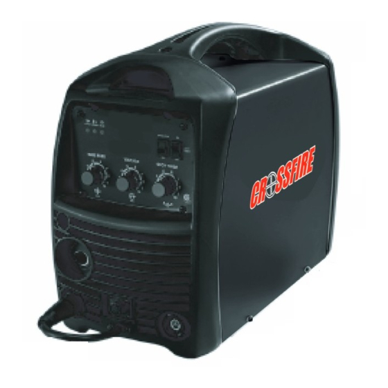
- Page 7 Please retain instructions for future reference. MIG WELDER Description The Crossfire MS 210SI is a DC inverter MIG welder. This unit uses 1Phase ~ 230V, 60HZ AC power. A 20 amp time delay fuse or circuit breaker is recommended.
- Page 8 MIG/STICK WELDER Operating Instructions and Parts Manual Specifications and Dimension Description Specification Model MS 210SI Input power Frequency Rated input current Rated input capacitance No-load voltage Rated working voltage MIG welding current 30~200 Rated duty cycle Welding current(10min)A 20%@200 10min/100% Efficiency η...
-
Page 9: Know Your Welder
MIG/STICK WELDER Operating Instructions and Parts Manual Know your Welder Power Work Alarm Power Cord Power Switch Indicator Indicator Indicator Wire speed adjust Spot Selector Welding Spool gun/Mig Voltage Selector Gas regulator Spot Time Gas hose Grounding cable with MIG gun clamp POWER INDICATOR When the machine is turned on, the power indicator will be on. - Page 10 MIG/STICK WELDER Operating Instructions and Parts Manual MIG GUN The welding wire is driven through the welding cable and MIG gun to the work piece. It is attached to the drive system. POWER SWITCH In the “OFF” position no power is being supplied. In the “ON”...
- Page 11 MIG/STICK WELDER Operating Instructions and Parts Manual be a #12 gauge cord at the smallest. Do not use an extension cord over 25 ft. in length. 3. Setting up the work piece 3.1 Welding positions There are two basic positions, for welding: Flat and Horizontal. Flat welding is generally easier, faster, and allows for better penetration.
- Page 12 MIG/STICK WELDER Operating Instructions and Parts Manual 4. Ground clamp connection Clear any dirt, rust, scale, oil or paint on the ground clamp. Make certain you have a good solid ground connection. A poor connection at the ground clamp will waste power and heat. Make sure the ground clamp touches the metal.
- Page 13 MIG/STICK WELDER Operating Instructions and Parts Manual -Do not touch cylinder with MIG gun. -Do not weld on the cylinder. -Always secure cylinder upright to a cart or stationary object. -Keep cylinders away from welding or electrical circuits. -Use the proper regulators, gas hose and fittings for the specific application.
-
Page 14: Operation
MIG/STICK WELDER Operating Instructions and Parts Manual spatter, a smooth weld bead will be difficult to obtain. Avoid unnecessary gas loss by closing the tank valve when finished welding. 6.3. Gas selection Different materials require different shielding gas when MIG welding, refer to the set up chart inside the wire feed compartment. - Page 15 MIG/STICK WELDER Operating Instructions and Parts Manual 3. Position the torch to the work piece There are two angles of the torch nozzle in relation to the work piece that must be considered when welding. 3.1. Angle A can be varied, but in most cases the optimum angle will be 60 degrees, the point at which the torch handle is parallel to the work piece.
-
Page 16: Welding Techniques
MIG/STICK WELDER Operating Instructions and Parts Manual 5.2. Select a heat setting. Refer to set up chart. 5.3. Hold the torch in one hand, allowing the nozzle to rest on the edge of the work piece farthest away from you, and at an angle similar to that which will be used when welding. - Page 17 MIG/STICK WELDER Operating Instructions and Parts Manual Travel speed is the rate at which the torch is being pushed or pulled along the weld joint. For a fixed heat setting, the faster the travel speed, the lower the penetration and the lower and narrower the finished weld bead. Likewise, the slower the travel speed, the deeper the penetration and the higher and wider the finished weld bead.
- Page 18 MIG/STICK WELDER Operating Instructions and Parts Manual HORIZONTAL POSITION Is performed very much the same as the flat weld except that angle B (see HOLDING THE TORCH) is such that the wire, Directed more toward the metal above the weld joint is to help prevent the weld puddle from running downward while still allowing slow enough travel speed .A good starting point for angle B is about 30 degrees DOWN from being perpendicular to the work piece...
- Page 19 MIG/STICK WELDER Operating Instructions and Parts Manual between the two pieces of metal that will have to be welded closed. In most cases more than one pass or bead will need to be laid into the joint to close the “V”.
- Page 20 MIG/STICK WELDER Operating Instructions and Parts Manual 6.5 Spot welding There are three methods of spot welding: Burn-Through, Punch and Fill, and Lap. Each has advantages and disadvantages depending on the specific application as well as personal preference. 1. The BURN-THROUGH METHOD welds two overlapped pieces of metal together by burning through the top piece and into the bottom piece.
-
Page 21: Troubleshooting Chart
MIG/STICK WELDER Operating Instructions and Parts Manual Trouble shooting Chart Breakdown Analysis Solutions Voltage is too high Switch off power source; Check (≥15%) the main supply; Restart welder when power recovers to normal Voltage is too low state. (≤15%) Poor ventilation lead Improve the ventilation condition. - Page 22 MIG/STICK WELDER Operating Instructions and Parts Manual Too thin power Change the power cable cable makes the power unstable Too low input increase the input voltage voltage Wire will not feed Clean or replace the liner and the torch tip Ground cable break Connect ground cable arc can’t be...
- Page 23 MIG/STICK WELDER Operating Instructions and Parts Manual Main Circuit chart -15V +15V...
-
Page 24: Spare Part List
MIG/STICK WELDER Operating Instructions and Parts Manual Spare Part List Repair Parts List CODE Description 2.05.08.126 Handle 1.1.01.01.0151 Enclosure 2.07.55.616 Gas valve plinth 2.07.80.001 Rocker Switch 1.2.07.02.3866 Gas valve wiring harness 1.1.01.03.1663 Back panel 1.2.07.02.3812 1.1.05.02.0516 Main control board... - Page 25 MIG/STICK WELDER Operating Instructions and Parts Manual 1.1.05.02.0200 Control board 2.07.57.817 Gas/water quick connector 2.07.40.740 Wire feeder 1.1.01.04.1358 Bottom 2.20.02.261 Gun plug 2.05.05.154 Front panel 1.2.07.02.3867 Output connector wiring harness 2.07.57.967 Europe type quick socket 2.03.40.764 Trigger switch wiring harness 1.2.08.02.0471 “-”...
- Page 26 MIG/STICK WELDER Operating Instructions and Parts Manual Service, Maintenance, Transportation and Storage The welder needs regular maintenance as following: Periodically clean dust, dirt, grease, etc. from your welder. Every six months, or as necessary, remove the cover panel from the welder and air-blow any dust and dirt that may have accumulated inside the welder.
Need help?
Do you have a question about the MS 210Si and is the answer not in the manual?
Questions and answers