Table of Contents
Advertisement
Quick Links
Advertisement
Table of Contents

Subscribe to Our Youtube Channel
Related Manuals for Crossfire TRION 250 HD


Summary of Contents for Crossfire TRION 250 HD
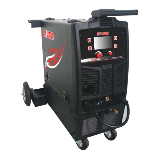
- Page 1 TRION 250 HD OWNER’S MANUAL WARNING: Read carefully and understand all ASSEMBLY AND OPERATION INSTRUCTIONS before operating. Failure to follow the safety rules and other basic safety precautions may result in serious personal injury. Revision 2020-08-21...
-
Page 2: Table Of Contents
Brief introduction..........12 Technical Specifications......12-14 Technical Data..........15 Operation method Operational approach........ 16-19 Common fault and elimination methods Spare part list ..........20 Quick-wear part list ........21-22 Common fault and elimination methods..23-24 Main Circuit chart ........25 Complete set specification .....26 CROSSFIRE Warranty .......27... -
Page 3: Safe Operation
“Danger” indicates an imminently hazardous situation which, if not avoided, “Warning!” indicates a possible hazardous situation which, if not avoided, could “Caution” indicates a possible hazardous situation which, if not avoided, may “Note!” indicates a situation which implies a risk of impaired welding result and damage to the equipment. - Page 4 fl AC welder with reduced open-load voltage. fi - IT and telecoms equipment - IT and telecoms equipment -Mains supply flame-resistant material (leather fl arc nor expose themselves to the arc rays or to hot spatter or material. your health.
- Page 5 fi supplied respirator. confi fi fi to prevent hazardous situations. fire hazards or overheat. fl position or in confined places. when in a welding area. fire. Remove fi Do not weld where fl fl atmosphere may contain fl gasoline). fl Keep a fi...
- Page 6 fi flame. gas cylinder. fittings condition. fi good condition. cylinder valve outlet. Hot parts can burn. Flying metal or dirt can injure eyes. When welding, chipping, wire flying metal. It can hurt your eyes. Noise can damage hearing. Noise can be from some working equipments or Moving parts can injure.
- Page 7 duty cycle to use the machine. Allow cooling period. flow to unit. fi fication.
- Page 8 è é é î î peut entraî Indique une situation qui implique un risque de perte de fi fi ûlures graves. Lorsque la machine est fi fil et î î fil de soudure sont fi É fi Connectez le câ maintenance.
- Page 9 fil) semi- ûr Alimentation secteur Câ Connectez le câ â â Blindage û ûler les yeux et la peau. fl non infl La soudure peut produire...
- Page 10 Travailler dans un espace confi fi fi ûr. Les étincelles de soudure et de coupe peuvent provoquer un incendie ou une explosion. Lors de la soudure, assurez-vous que le circuit de Assurez-vous que la zone est sûre avant toute soudure. Connectez le câ...
- Page 11 É fisant de personnes pour fixant sur un Gardez une distance sû flammes. toute autre source de chaleur â ç çus û avec la main nue ou la peau. ûlures. fi soudure.
- Page 12 înement. fi î utiliser la machine. mise en œuvre pour la certifi normes pour le Canada et les É...
-
Page 13: Brief Introduction
Summary 2.1 Brief introduction Inverter welder gas protection using meltable by the arc between the wire and the welders as a heat source to melt the wire and the base metal , to transport gas welding area to protect the arc melting of the wire , the pool and nearby base metal from the harmful effects of the surrounding air . - Page 14 * Relative humidity:when at 40℃:≤50%;when at 20℃:≤90%。 * Dust, acid , corrosive gas or matter in the air less than normal content Besides matter is produced in welding process. Place is not drastic motion. * Altitude less than 1000m * Keep from raining when it is used outdoor. 2.2.2 Power supply requirement * Service voltage waveform should be actual sine wave, frequency jitter is less than±1% of rated value.
- Page 15 MIG/MAG. TIG. MMA. 1ph, rated frequency 50Hz,operating frequency 60Hz. X:duty cycle. I1max.A:rated max input current. I1eff...A:max effective input current. I2:rated welding current. U0:rated no loading voltage U1:rated input voltage. U2:loading voltage ...V:unit of voltage ...A:unit of current ...%:unit of duty cycle ...A/...V to ...A/...V:output range。Min or max rated welding current and relevant loadingvoltage.
-
Page 16: Technical Data
2.3 Technical Data 2.3.1 Main technical data project unit TRION 250 voltage 1~230 frequency 50/60 Max rated input current Rated capacity 10.4 No Loading voltage Welding voltage 16~26.5 Rated duty cycle Welding Wire diameter Ф0.6~Ф1.2 Rated welding current(MIG) Rated welding current(Stick) 20~200 Current adjustment(Stick) Rated welding current(TIG) -
Page 17: Operation Method
Proper use and maintenance, to ensure good welding performance and prolong the life of the welder. Maintenance welder by professionals responsible, when the user encounters a failure can not be excluded or do not have the maintenance capability, should get in touch with CROSSFIRE or our agents, for repair, and service parts. - Page 18 3.1.6 Front Ctrl panel 1.LCD: Shows all process from function selection to welding. 2.Gas-check button: press the button and the gas supply system works. 3.Wire-check button:press the button and the wire supply system works. 4.Multi-function adjusting knob: For function selection; Press for confirming. Allows user to adjust the current and wire feeding speed accurately.
- Page 19 (4)Material thickness: Adjusting multi-function knob to select different material thickness. (5).Welding display:Shows all selected parameters. A.Under MIG welding, user can set wire feeding speed and voltage. Adjusting Multi-function knob to set electro-inductance, press the knob to progress basic parameter setting. Note: Note1:Basic parameter setting includes:Gas pre flow, slow wire feeding, gas post flow, operating, load and save function.
- Page 20 (6).Setting interface: It shows language setting, units setting, light setting, information and recover setting. (7).Alarm interface:It shows the machine is overloaded and the internal temperature is too high. Weld output will turn off automatically but the fan will still be working. When the internal temperature is decreased, the alarm interface will turn off and the machine will be ready to weld.
-
Page 21: Spare Part List
Common fault and elimination methods 4.1 Spare part list... -
Page 22: Quick-Wear Part List
4.2 Quick-wear part list Description Exploded view No Code Quantity 11020013424 Fixed Plate 20050170009 Plastic Hinge 11010012419 Housing 20050050294 Plastic Workbin 20070890232 DC Fan 11020016133 Cylinder Bracket 20070800027 Disconnector 11020011828 Switch Support 20050170013 Tension Disc 20040300009 Cable Gland 12070024440 Gas Valve Cord 12070020231 Fan Cord 11010032749... - Page 23 20050070036 Mecanum Wheels 20070570185 Quick connect receptacle 20030305457 Trigger Switch Cord 12070030075 Polarity Conversion cable 11010032750 Front shutter 20070570129 Gas connector 20030305458 Spool gun cord 20030305176 Foot Switch cord 20070110073 Potentiometer knob 20070110072 Potentiometer knob 11020012794 Panel support plate 11050070766 LCD panel 20050050301 Plastic Cover...
- Page 24 4.3 Common fault and elimination methods 4.3.1 failure analysis and troubleshooting (see Table 4) Failure Cause Failure Analysis troubleshooting Investigate the reasons of connecting No power power. Press the triggers, no wire 1 Torch switch is broken Change the torch switch Wire feeder current regulator Change potentiometer There is no-load voltage ,...
- Page 25 4.3.2 Common weld defects ( see Table 5 ) Weld defects Cause Analysis and Troubleshooting Wire and workpiece have excess oil, rust and water. CO2 gas shielded bad. (Low flow, lack of silico-manganese Vent Excess content in the wire, gas impurities, nozzle clogging, leakage, wind over speed) Wire and workpiece have excess oil, rust and water.
-
Page 26: Main Circuit Chart
Main Circuit chart TRION 250 inverter gas protection welder main circuit diagram (see Fig subject to change without notice) -
Page 27: Complete Set Specification
Complete set specification * Welder 1 pc * Product certification 1 pc * Warranty Card 1 pc * Product Manual 1 pc Optional accessories * Torch 1 pc * Gas hose 1 pc * Control cables, welding cables 1 pc * Ground cable (with ground clamp ) 1 pc * Small accessories ( hose clamps, tip , etc.) -
Page 28: 7 Crossfire Warranty
WARRANTY AND THE REMEDIES HEREIN ARE THE SOLE claim processing. Warranty period begins at the time AND EXCLUSIVE REMEDIES OF THE PURCHASER IN RESPECT TO CROSSFIRE PRODUCTS. IN NO EVENT SHALL CROSSFIRE WELDERS BE LIABLE FOR ALL INDIRECT, Keep your receipt as proof of purchase.
Need help?
Do you have a question about the TRION 250 HD and is the answer not in the manual?
Questions and answers