
Related Manuals for Eclipse UDC2500 Limit


Summary of Contents for Eclipse UDC2500 Limit
- Page 1 Information Guide 925-1 08/2005 Eclipse Universal Digital Controller UDC2500 Limit Control Model...
- Page 2 UDC2500 Universal Digital Limit ControllerProduct Manual 8/05...
- Page 3 About This Document Abstract This document provides descriptions and procedures for the Installation, Configuration, Operation, and Troubleshooting of your UDC2500 Controller. Symbol Definitions The following table lists those symbols used in this document to denote certain conditions. Symbol Definition This CAUTION symbol on the equipment refers the user to the Product Manual for additional information.
-
Page 4: Table Of Contents
Contents INTRODUCTION ....................1 Overview............................1 1.1.1 Function of keys........................3 Process Instrument Explorer Software....................4 CE Conformity (Europe).........................6 INSTALLATION..................... 7 Overview............................7 Condensed Specifications .......................8 Model Number Interpretation .......................11 Limit and Alarm Relay Contact Information ................13 Mounting............................14 Wiring ............................16 2.6.1 Electrical Considerations ....................16 Wiring Diagrams...........................18 Limit Control Application Diagram....................25 CONFIGURATION.................... - Page 5 Operating Your Limit Controller ....................51 Alarm Setpoints ..........................54 INPUT CALIBRATION..................55 Overview............................55 Minimum and Maximum Range Values ..................56 Preliminary Information........................58 Input 1 Set Up Wiring........................59 Input 1 Calibration Procedure .......................63 Restore Input Factory Calibration....................64 OUTPUT CALIBRATION..................67 Overview............................67 Auxiliary Output Calibration ......................67 Restore Output Factory Calibration ....................69 TROUBLESHOOTING/SERVICE................
- Page 6 10.1 Overview ...........................97 10.2 Reading Control Data........................99 10.3 Miscellaneous Read Onlys ......................99 10.3.1 Register Addresses for Read Onlys ................99 10.4 Configuration Parameters......................100 10.4.1 Lock..........................100 10.4.2 Limit ..........................101 10.4.3 Input 1...........................102 10.4.4 Options .........................104 10.4.5 Communications......................105 10.4.6 Alarms ..........................106 10.4.7 Display..........................108 10.5 Modbus RTU Exception Codes....................109 ETHERNET TCP/IP ...................
- Page 7 Tables Table 2-1 Condensed Specifications _____________________________________________________ 8 Table 2-2 Limit Relay Contact Information _______________________________________________ 13 Table 2-3 Alarm Relay Contact Information ______________________________________________ 13 Table 2-4 Mounting Procedure_________________________________________________________ 15 Table 2-5 Permissible Wiring Bundling__________________________________________________ 17 Table 2-6 Terminals for connecting a UDC to a MDI Compliant Hub or Switch __________________ 23 Table 2-7 Terminals for connecting a UDC directly to a PC utilizing a straight-through cable ________ 23 Table 3-1 Configuration Topics ________________________________________________________ 26 Table 3-2 Configuration Prompt Hierarchy _______________________________________________ 27...
- Page 8 Table 8-2 Parts Not Shown____________________________________________________________ 86 Table 9-1 Integer Parameter Type ______________________________________________________ 89 Table 9-2 Floating Point Parameter Type_________________________________________________ 89 Table 9-3 Register Address Format for Function Code 20____________________________________ 91 Table 9-4 Register Address Format for Function Code 21____________________________________ 95 Table 10-1 Control Data Parameters ____________________________________________________ 99 Table 10-2 Miscellaneous Read Onlys___________________________________________________ 99 Table 10-3 Set-up Group Lock________________________________________________________ 100...
- Page 9 Figures Figure 1-1 UDC2500 Operator Interface __________________________________________________ 2 Figure 1-2 Screen capture of Process Instrument Explorer running on a Pocket PC _________________ 4 Figure 1-3 Depiction of infrared communications ___________________________________________ 5 Figure 2-1 Model Number Interpretation _________________________________________________ 12 Figure 2-2 Mounting Dimensions (not to scale)____________________________________________ 14 Figure 2-3 Mounting Method __________________________________________________________ 15 Figure 2-4 Composite Wiring Diagram __________________________________________________ 18 Figure 2-5 Mains Power Supply________________________________________________________ 19...
-
Page 11: Introduction
1 Introduction 1.1 Overview Function UDC2500 Limit Controllers accept input signals from any of several types of external sensors such as Thermocouples (T/Cs) and Resistance Temperature Detectors (RTDs). It conditions these signals, as necessary, to derive the equivalent Process Variable (PV) value that drives various circuits in the controller. -
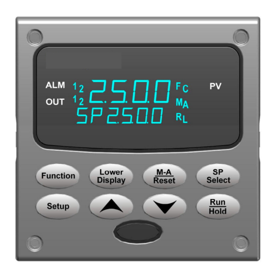
Page 12: Figure 1-1 Udc2500 Operator Interface
Introduction When the PV signal returns to a value above the limit set point, the controller can be reset manually using the RESET key or Contact Input Option. Easy to read displays The dedicated vacuum fluorescent displays with multi-language prompts make the operator interface easy to read, understand and operate. -
Page 13: Function Of Keys
Introduction 1.1.1 Function of keys Table 1-1 shows each key on the operator interface and defines its function. Table 1-1 Function of Keys Function • Places the controller in the Configuration Set Up group select mode. Sequentially displays Set Up groups and allows the FUNCTION key to Setup Setup display individual functions in each Set Up group. -
Page 14: Process Instrument Explorer Software
Introduction 1.2 Process Instrument Explorer Software Overview Process Instrument Explorer lets you configure your instrument on a desktop/laptop or Pocket PC. For details see Process Instrument Explorer manual #51-52-25-131. Features • Create configurations with intuitive software program running on either a Pocket PC, a Desktop or a laptop computer. -
Page 15: Figure 1-3 Depiction Of Infrared Communications
Introduction Infrared communications The infrared connection provides a non-intrusive wireless connection with the instrument and maintains NEMA4X AND IP66 integrity. No need to get access to the back of the controller to communicate with the instrument, no need to take your screw driver to wire the communication cable, no wiring mistake possible. -
Page 16: Ce Conformity (Europe)
Introduction 1.3 CE Conformity (Europe) This product is in conformity with the protection requirements of the following European Council Directives: 73/23/EEC , the Low Voltage Directive, and 89/336/EEC , the EMC Directive. Conformity of this product with any other “CE Mark” Directive(s) shall not be assumed. -
Page 17: Installation
Installation 2 Installation 2.1 Overview Introduction Installation of the UDC2500 consists of mounting and wiring the controller according to the instructions given in this section. Read the pre-installation information, check the model number interpretation (Subsection 2.3), and become familiar with your model selections, then proceed with installation. -
Page 18: Condensed Specifications
Installation Pre-installation Information If the controller has not been removed from its shipping carton, inspect the carton for damage then remove the controller. • Inspect the unit for any obvious shipping damage and report any damage due to transit to the carrier. •... - Page 19 Installation Electromechanical Relay Controller Output Types SPDT contacts. Both Normally Open and Normally Closed contacts are brought out to the rear terminals. Internally socketed. Resistive Load: 5 amps @ 120 Vac or 240 Vac or 30 Vdc ϕ Inductive Load (cos = 0.4): 3 amps @ 130 Vac or 250 Vac Inductive Load (L/R = 7 msec): 3.5 amps @ 30 Vdc Motor: 1/6 H.P.
- Page 20 Installation Weight 3 lbs. (1.3 kg) Environmental and Operating Conditions Parameter Reference Rated Operative Transportation and Limits Storage Ambient Temperature 25 ± 3 °C 15 to 55 °C 0 to 55 °C –40 to 66 °C 77 ± 5 °F 58 to 131 °F 32 to 131 °F –40 to 151 °F...
-
Page 21: Model Number Interpretation
Installation 2.3 Model Number Interpretation Introduction Write your controller’s model number in the spaces provided below and circle the corresponding items in each table. This information will also be useful when you wire your controller. KEY NUMBER - UDC2500 Single Loop Controller Description Selection Availability... -
Page 22: Figure 2-1 Model Number Interpretation
Installation Limit Controller Restrictions/Comments: 1. FM approved units with communications are limited to read only. 2. FM approved units are restricted to TC and RTD type inputs. 3. UL listed for regulatory use only. _ L _ Input 2 Not Available with Limit Model Figure 2-1 Model Number Interpretation UDC2500 Universal Digital Limit ControllerProduct Manual 8/05... -
Page 23: Limit And Alarm Relay Contact Information
Installation 2.4 Limit and Alarm Relay Contact Information Limit Relay ATTENTION The Limit relay is designed to operate in a Failsafe mode. This results in momentary (5 seconds maximum) limit action when power is initially applied, until the unit completes self- diagnostics. -
Page 24: Mounting
Installation 2.5 Mounting Physical Considerations The controller can be mounted on either a vertical or tilted panel using the mounting kit supplied. Adequate access space must be available at the back of the panel for installation and servicing activities. • Overall dimensions and panel cutout requirements for mounting the controller are shown in Figure 2-2. -
Page 25: Table 2-4 Mounting Procedure
Installation Mounting Method Before mounting the controller, refer to the nameplate on the outside of the case and make a note of the model number. It will help later when selecting the proper wiring configuration. Mounting Clips Attach screws and washers here for water protection Figure 2-3 Mounting Method... -
Page 26: Wiring
Installation 2.6 Wiring 2.6.1 Electrical Considerations Line voltage wiring This controller is considered “rack and panel mounted equipment” per EN61010-1, Safety Requirements for Electrical Equipment for Measurement, Control, and Laboratory Use, Part 1: General Requirements. Conformity with 72/23/EEC, the Low Voltage Directive requires the user to provide adequate protection against a shock hazard. -
Page 27: Table 2-5 Permissible Wiring Bundling
Installation Electrical Noise Precautions Electrical noise is composed of unabated electrical signals which produce undesirable effects in measurements and control circuits. Digital equipment is especially sensitive to the effects of electrical noise. Your controller has built-in circuits to reduce the effect of electrical noise from various sources. If there is a need to further reduce these effects: •... -
Page 28: Wiring Diagrams
Installation 2.7 Wiring Diagrams Identify Your Wiring Requirements To determine the appropriate diagrams for wiring your controller, refer to the model number interpretation in this section. The model number of the controller can be found on the outside of the case. Wiring the Controller Using the information contained in the model number, select the appropriate wiring diagrams from the composite wiring diagram below. -
Page 29: Figure 2-5 Mains Power Supply
Installation Ground AC/DC Line Neutral L2/N Voltage PROTECTIVE BONDING (grounding) of this controller and the enclosure in which it is installed, shall be in accordance with National and local electrical codes. To minimize electrical noise and transients that may adversely affect the system, supplementary bonding of the controller enclosure to local ground using a No. -
Page 30: Figure 2-6 Input 1 Connections
Installation Input #1 Millivolt or Volts Thermocouple except 0-10 Volts Use Thermocouple extension wire only source mV or Volt source – – – – 0-10 Volts Milliamps Thermocouple Differential Use Thermocouple extension wire only – 100K 0–10 Xmitter Volt – 250 Ω... -
Page 31: Figure 2-7 Electromechanical Relay Output
Installation N.C. Output Load Relay Load Relay#1 Supply N.O. To terminal L2/N Power 19 or 21 N.C. Load Relay Load Alarm Supply Relay#2 N.O. To terminal Power 4 or 6 N.C. Load Alarm Relay Load Relay#1 Supply N.O. To terminal Power 7 or 9 Electromechanical relays are rated at Amps @120 Vac or 30 Vdc and 2.5 Amps at 240 Vac. -
Page 32: Figure 2-9 Open Collector Output
Installation Time Simplex Customer Supplied Electromechanical relay Output #1 – L2/N – – N.C. Alarm Customer Supplied Load Relay Load Relay#2 Solid-State relay Supply N.O. To terminal Power 4 or 6 N.C. Alarm Load Relay Load Relay#1 Supply N.O. To terminal Power 7 or 9 Open collector outputs are internally powered at +30 Vdc. -
Page 33: Table 2-6 Terminals For Connecting A Udc To A Mdi Compliant Hub Or Switch
Installation COMMUNIC ATION MASTER COMMUNIC ATION MASTER COMMUNIC ATION MASTER COMMUNIC ATION MASTER 3 3 3 3 OR SWITCH OR SWITCH OR SWITCH OR SWITCH SHLD SHLD SHLD SHLD RXD+ TXD– RXD+ TXD– RXD- TXD+ TXD- TXD+ RXD– RXD + RXD- TXD+ TXD- TXD+ RXD–... -
Page 34: Figure 2-12 Auxiliary Output And Digital Inputs Option Connections
Installation Auxiliary Output Digital Inputs Auxiliary Digital Load Input #1 0 - 1000 Ω Connect shield to ground at one Connect shield end only. to ground at one end only. xxxx Figure 2-12 Auxiliary Output and Digital Inputs Option Connections 2 Wire Transmitter Configure: A2S1TY = NONE... -
Page 35: Limit Control Application Diagram
Installation 2 Wire Transmitter Configure: AUXOUT = OUT Auxiliary Output Calibration ZEROVAL = 4095 SPANVAL = 4095 12 + 26 + 250 Ω 13 - 27 - AUXILIARY OUTPUT INPUT 1 xxxx If necessary, install a zener diode here to reduce voltage at the transmitter. -
Page 36: Configuration
Configuration 3 Configuration 3.1 Overview Introduction Configuration is a dedicated operation where you use straightforward keystroke sequences to select and establish (configure) pertinent control data best suited for your application. To assist you in the configuration process, there are prompts that appear in the upper and lower displays. -
Page 37: Configuration Prompt Hierarchy
Configuration 3.2 Configuration Prompt Hierarchy Table 3-2 Configuration Prompt Hierarchy Set Up Group Function Prompts LOCK SECUR LOCK LIMIT LOorHI POWRUP SPMAX SPMIN DISPLY INPUT1 IN1TYP XMITR1 IN1 HI IN1 LO BIAS 1 FILTR1 BRNOUT EMISS OPTIONS DIGIN1 AUXOUT ComADR ComSTA IRENAB BAUD... -
Page 38: Configuration Procedure
Configuration 3.3 Configuration Procedure Introduction Each of the Set Up groups and their functions are pre-configured at the factory. The factory settings are shown in Section 3.11. If you want to change any of these selections or values, follow the procedure in Table 3-3. -
Page 39: Lock Set Up Group
Configuration 3.4 Lock Set Up Group Introduction The Lock Set Up group contains the Function parameters that will allow your controller to protect Configuration and Calibration data. Because this group contains functions that have to do with Security and Lockout, it is best to configure this group last, after all the other configuration data has been loaded. -
Page 40: Limit Set Up Group
Configuration 3.5 Limit Set Up Group Introduction This data deals with the type of Limit Control you want, power up Logic, setpoint high and low limits, and the default display function Prompts Table 3-5 LIMIT Group Function Prompts Function Prompt Selection or Range of Setting Parameter Lower Display... -
Page 41: Input 1 Set Up Group
Configuration 3.6 Input 1 Set Up Group Introduction This data deals with various parameters required to configure Input 1. Function Prompts Table 3-6 INPUT 1 Group Function Prompts Function Prompt Selection or Range of Setting Parameter Lower Display Upper Display Definition IN1TYP INPUT 1 ACTUATION TYPE –... - Page 42 Configuration Function Prompt Selection or Range of Setting Parameter Lower Display Upper Display Definition XMITR1 TRANSMITTER CHARACTERIZATION— This selection lets you instruct the controller to characterize a linear input to represent a non-linear one. If characterization is performed by the transmitter itself, then select LIN (Linear).
- Page 43 Configuration Function Prompt Selection or Range of Setting Parameter Lower Display Upper Display Definition −999 to 9999 floating in INPUT 1 LOW RANGE VALUE in IN1 LO engineering units is displayed for all inputs engineering units but can only be configured for linear or square root transmitter characterization.
- Page 44 Configuration Function Prompt Selection or Range of Setting Parameter Lower Display Upper Display Definition 0.01 to 1.00 EMISSIVITY is a correction factor applied to EMISS the Radiamatic input signal that is the ratio of the actual energy emitted from the target to the energy which would be emitted if the target were a perfect radiator.
-
Page 45: Options Set Up Group
Configuration Options Set Up Group Introduction The Options group lets you configure the remote mode switch (Digital Inputs) to a specific contact closure response, or configure the Auxiliary Output to be a specific selection with desired scaling. Function Prompts Table 3-7 OPTION Group Function Prompts Function Prompt Selection or Range of Setting Parameter... - Page 46 Configuration Function Prompt Selection or Range of Setting Parameter Lower Display Upper Display Definition Auxiliary Output = 50% – 7.5% = 42.5% 0_PCT AUXILIARY OUTPUT LOW SCALING Value in Engineering Units FACTOR—Use a value in engineering units to represent all AUX OUT parameters except output.
-
Page 47: Communications Set Up Group
Configuration Communications Set Up Group Introduction The Communications group lets you configure the controller to be connected to a host computer via Modbus® or Ethernet TCP/IP protocol. Introduction A controller with a communications option looks for messages from the host computer. If these messages are not received within the configured shed time, the controller will SHED from the communications link and return to stand-alone operation. - Page 48 Configuration Function Prompt Selection or Range of Parameter Lower Display Setting Definition Upper Display TX_DLY 1 to 500 milliseconds TX DELAY—Configurable response-delay timer allows you to force the UDC to delay its response for a time period of from 1 to 500 milliseconds compatible with the host system hardware/software.
- Page 49 Configuration Function Prompt Selection or Range of Parameter Lower Display Setting Definition Upper Display SHD_SP SHED SETPOINT RECALL Note: If SHEDENAB=DISABLE, this prompt will not be configurable. TO LSP—Controller will use last local or remote setpoint used. TO CSP—When in “slave” mode, the controller will store the last host computer setpoint and use it at the Local setpoint.
-
Page 50: Alarms Set Up Group
Configuration Alarms Set Up Group Introduction An alarm is an indication that an event that you have configured (for example—Process Variable) has exceeded one or more alarm limits. There are two alarms available. Each alarm has two setpoints. You can configure each of these two setpoints to alarm on various controller parameters. - Page 51 Configuration Function Prompt Selection or Range of Setting Parameter Lower Display Upper Display Definition Thermocouple Input is in imminent danger of failing. Not valid for input types other than Thermocouple. ALARM 1 SETPOINT 1 VALUE—This is the A1S1VA Value in engineering units value at which you want the alarm type chosen in prompt A1S1TYPE to actuate.
- Page 52 Configuration Function Prompt Selection or Range of Setting Parameter Lower Display Upper Display Definition Value in engineering units A2S2TY ALARM 2 SETPOINT 2 TYPE—Select what you want Setpoint 2 of Alarm 2 to represent. The selections are the same as A1S1TYPE. ATTENTION Not applicable with Relay Duplex unless using Dual Relay PWA.
- Page 53 Configuration Function Prompt Selection or Range of Setting Parameter Lower Display Upper Display Definition BLOCK ALARM BLOCKING—Prevents nuisance alarms when the controller is first powered up. The alarm is suppressed until the parameter gets to the non-alarm limit or band. Alarm blocking affects both alarm setpoints.
-
Page 54: Display Set Up Group
Configuration 3.10 Display Set Up Group Introduction This group includes selections for Decimal place, Units of temperature, Language and Power frequency. Function Prompts Table 3-10 DISPLY Group Function Prompts Function Prompt Selection or Range of Setting Parameter Lower Display Upper Display Definition DECIMAL POINT LOCATION—This DECMAL... -
Page 55: Configuration Record Sheet
Configuration 3.11 Configuration Record Sheet Enter the value or selection for each prompt on this sheet so you will have a record of how your controller was configured. Group Function Value or Factory Group Function Value or Factory Prompt Prompt Selection Setting Prompt... -
Page 56: Operating The Limit Controller
Operating the Limit Controller 4 Operating the Limit Controller 4.1 Overview Introduction This section gives you all the information necessary to help you monitor your controller including an Operator Interface overview, how to lockout changes to the controller, entering a security code, and monitoring the displays. What's in this section? The following topics are covered in this section. -
Page 57: Operator Interface
Operating the Limit Controller 4.2 Operator Interface Introduction Figure 5-1 is a view of the Operator Interface. A description of the displays and indicators is included. Figure 4-1 Operator Interface 4.3 Entering a Security Code Introduction The level of keyboard lockout may be changed in the Set Up mode. However, knowledge of a security code number (0 to 9999) may be required to change from one level of lockout to another. -
Page 58: Lockout Feature
Operating the Limit Controller Table 4-1 Procedure to Enter a Security Code Step Operation Press Result Enter Set Up Upper Display = SET UP Setup Setup Mode Lower Display = LOCK Select any Set Upper Display = 0 Function Function Function Up Group Lower Display = SECUR... -
Page 59: Monitoring Your Limit Controller
Operating the Limit Controller 4.5 Monitoring Your Limit Controller Annunciators The following annunciator functions have been provided to help monitor the controller: Table 4-2 Annunciators Annunciator Indication ALM 1 2 A visual indication of each alarm Blinking 1 indicates alarm latched and needs to be acknowledged before extinguishing when the alarm condition ends F or C A visual indication of the temperature units... -
Page 60: Table 4-3 Error Messages
Operating the Limit Controller Diagnostic Error Messages 2500 performs background tests to verify data and memory integrity. If there is a malfunction, an error message will be displayed. In the case of more than one simultaneous malfunction, the messages will be displayed sequentially on the lower display. -
Page 61: Operating Your Limit Controller
Operating the Limit Controller Operating Your Limit Controller Operating Principles The Limit Controller accepts signals from such sources as Thermocouples (T/Cs), Resistance Temperature Detectors (RTDs), and Radiamatics. The equivalent PV signal is compared with the Limit set point. If above (Hi Limit) or below (Lo Limit), a limit output relay is de-energized. - Page 62 Operating the Limit Controller How to set a limit setpoint Step Operation Press Result Display Press the "Lower Display" key till SP appears. Lower Lower Lower setpoint Display Display Display Enter the Limit Set the SP, using the Up & Down arrow keys, to the desired Limit Setpoint Setpoint Store the limit...
-
Page 63: Table 4-4 Using Contact Input Option
Operating the Limit Controller How to Reset the Latching Relay The latching relay cannot be reset until the PV input signal drops below the high set point (High Limit) or rises above the low set point (Low Limit) value. Press the key or make contact closure of an external switch if the External M-A RESET Reset option is present. -
Page 64: Alarm Setpoints
Operating the Limit Controller 4.7 Alarm Setpoints Introduction An alarm consists of a relay contact and an operator interface indication. The alarm relay is de-energized if setpoint 1 or setpoint 2 is exceeded. The alarm relay is energized when the monitored value goes into the allowed region by more than the hysteresis. -
Page 65: Input Calibration
Input Calibration 5 Input Calibration WARNING—SHOCK HAZARD INPUT CALIBRATION MAY REQUIRE ACCESS TO HAZARDOUS LIVE CIRCUITS, AND SHOULD ONLY BE PERFORMED BY QUALIFIED SERVICE PERSONNEL. MORE THAN ONE SWITCH MAY BE REQUIRED TO DE-ENERGIZE UNIT BEFORE CALIBRATION. 5.1 Overview Introduction This section describes the field calibration procedures for Input 1. -
Page 66: Minimum And Maximum Range Values
Input Calibration Calibration Steps Use the following steps when calibrating an input. Step Action Find the minimum and maximum range values for your PV input range from Table 5-1. Disconnect the field wiring and find out what equipment you will need to calibrate. Wire the calibrating device to your controller according to the set up wiring instructions for your particular input (Subsection 5.4). - Page 67 Input Calibration Sensor Type PV Input Range Range Values °F °C 100 % 0 to 3100 –18 to 1704 –0.092 mV 17.998 mV -300 to 700 –184 to 371 –5.341 mV 19.097 mV -200 to 500 –129 to 260 –4.149 mV 12.574 mV T (low) W5W26...
-
Page 68: Preliminary Information
Input Calibration 5.3 Preliminary Information Disconnect the Field Wiring Tag and disconnect any field wiring connected to the input terminals on the rear of the controller. 25 R Input 1 26 + Connections 27 – Input 1 Figure 5-1 Input 1 Wiring Terminals Equipment Needed Table 5-2 lists the equipment you will need to calibrate the specific types of inputs that are listed in the table. -
Page 69: Input 1 Set Up Wiring
Input Calibration 5.4 Input 1 Set Up Wiring Thermocouple Inputs Using an Ice Bath Refer to Figure 5-2 and wire the controller according to the procedure given in Table 5-3. Table 5-3 Set Up Wiring Procedure for Thermocouple Inputs Using an Ice Bath Step Action Connect the copper leads to the calibrator. -
Page 70: Table 5-4 Set Up Wiring Procedure For Thermocouple Inputs Using Thermocouple Source
Input Calibration Thermocouple Inputs Using a Thermocouple Source Refer to Figure 5-3 and wire the controller according to the procedure given in Table 5-4.. Table 5-4 Set Up Wiring Procedure for Thermocouple Inputs using Thermocouple Source Step Action Connect the thermocouple extension wires to the terminals for Input #1 as shown in Figure 5-3. -
Page 71: Table 5-6 Wiring Connections For Radiamatic, Thermocouple Differential, Millivolts Or Volts
Input Calibration Radiamatic, Millivolts, Volts or Thermocouple Differential Inputs Refer to Figure 5-5 and wire the controller according to the procedure given in Table 5-6. Table 5-6 Wiring Connections for Radiamatic, Thermocouple Differential, Millivolts or Volts (Except 0 to 10 Volts) Step Action Connect the copper leads from the calibrator to the Input #1 terminals as shown in... -
Page 72: Table 5-7 Set Up Wiring Procedure For 0 To 10 Volts
Input Calibration 0 to 10 Volts Refer to Figure 5-6 and wire the controller according to the procedure given in Table 5-7. Table 5-7 Set Up Wiring Procedure for 0 to 10 Volts Step Action Connect the copper leads from the calibrator to the Input #1 terminals as shown in Figure 5-6. -
Page 73: Input 1 Calibration Procedure
Input Calibration 5.5 Input 1 Calibration Procedure Preliminary Steps • Apply power and allow the controller to warm up for 30 minutes before you calibrate. • Please read Subsection 5.4 – Input 1 Set Up Wiring before beginning the procedure. •... -
Page 74: Restore Input Factory Calibration
Input Calibration Step Operation Press Result Lower Display = IN1SPN • Adjust your calibration device to an output signal equal to the 100 % range value for your particular input sensor. See Table 5-1 for Voltage, Degrees, or Resistance equivalents for 100 % range values. •... -
Page 75: Table 5-10 Restore Input Factory Calibration
Input Calibration ATTENTION A restored factory calibration overwrites any previous field calibration done for the input and may change the High and Low Range Limits. Protect your field calibration from accidental overwrites by configuring the appropriate LOCKOUT selection after calibration. See the Section 3 - Configuration for specific instructions to set the lockout. - Page 76 Input Calibration UDC2500 Universal Digital Limit ControllerProduct Manual 8/05...
-
Page 77: Output Calibration
Output Calibration 6 Output Calibration 6.1 Overview Introduction This section describes the field calibration procedures for the Auxiliary Output. What's in this section? The following topics are covered in this section. TOPIC See Page 6.1 Overview 6.2 Auxiliary Output Calibration 6.3 Restore Output Factory Calibration WARNING—SHOCK HAZARD OUTPUT CALIBRATION MAY REQUIRE ACCESS TO HAZARDOUS LIVE CIRCUITS, AND... -
Page 78: Table 6-1 Set Up Wiring Procedure For Auxiliary Output
Output Calibration Table 6-1 Set Up Wiring Procedure for Auxiliary Output Step Action Apply power and allow the controller to warm up 30 minutes before you calibrate. Set LOCK in the Tuning Set Up group to NONE. Tag and disconnect the field wiring, at the rear of the controller, from terminals 12 (+) and 13 (–). -
Page 79: Restore Output Factory Calibration
Output Calibration Procedure The procedure for calibrating the auxiliary output is listed in Table 6-2. The numeric codes are also listed. Make sure “LOCK” in the Lock Set Up group is set to “NONE” (see Subsection 3.4). Table 6-2 Auxiliary Output Calibration Procedure Step Operation Press... -
Page 80: Table 6-3 Restore Factory Calibration
Output Calibration ATTENTION A restored factory calibration overwrites any previous field calibration done for the output. Protect your field calibration from accidental overwrites by configuring the appropriate LOCKOUT selection after calibration. See Section 3 - Configuration for specific instructions to set the lockout. Table 6-3 Restore Factory Calibration Step Operation... -
Page 81: Troubleshooting/Service
Troubleshooting/Service 7 Troubleshooting/Service 7.1 Overview Introduction Instrument performance can be adversely affected by installation and application problems as well as by hardware problems. We recommend that you investigate the problems in the following order: • installation related problems • application related problems •... -
Page 82: Troubleshooting Aids
Troubleshooting/Service noise, connecting external equipment to the controller, and shielding and routing external wiring. ATTENTION System noise induced into the controller will result in diagnostic error messages recurring. If the diagnostic error messages can be cleared, it indicates a “soft” failure and is probably noise related. If system noise is suspected, completely isolate the controller from all field wiring. -
Page 83: Table 7-1 Procedure For Identifying The Software Version
Troubleshooting/Service Determining the software version Table 7-1 lists the procedure for identifying the software version number. Table 7-1 Procedure for Identifying the Software Version Step Operation Press Result Select Upper Display = READ Setup Setup STATUS Lower Display = STATUS Set Up Group Read the software You will see:... -
Page 84: Power-Up Tests
Troubleshooting/Service 7.3 Power-up Tests What happens at power-up When power is applied, the controller will run three diagnostic tests. After these tests are completed, “TEST DONE” is displayed. Test Failures If one or more of these tests fail, the controller will go to the Failsafe Manual Mode, and FAILSF will flash in the lower display and a message indicating which test failed will appear in the lower display. -
Page 85: Background Tests
Troubleshooting/Service Background Tests Introduction The UDC2500 performs ongoing background tests to verify data and memory integrity. If there is a malfunction, a diagnostic message will be displayed (blinking) in the lower display. In the case of simultaneous malfunctions, the messages will appear in sequence in the lower display. - Page 86 Troubleshooting/Service Lower Reason for Failure How to Correct the Problem Display PV out of range. 1. Make sure the input signal is correct. PV LIM PV = INP1 x RATIO1+ INP1 BIAS 2. Make sure the Ratio and Bias settings are correct.
-
Page 87: Controller Failure Symptoms
Troubleshooting/Service 7.6 Controller Failure Symptoms Introduction In addition to the error message prompts, there are failure symptoms that can be identified by noting how the controller displays and indicators are reacting. Symptoms Compare your symptoms with those shown in Table 7-4. Table 7-4 Controller Failure Symptoms Upper Lower... -
Page 88: Troubleshooting Procedures
Troubleshooting/Service 7.7 Troubleshooting Procedures Introduction The troubleshooting procedures are listed in numerical order as they appear in Table 7-4. Each procedure lists what to do if you have that particular failure and how to do it or where to find the data needed to accomplish the task. WARNING—SHOCK HAZARD TROUBLESHOOTING MAY REQUIRE ACCESS TO HAZARDOUS LIVE CIRCUITS, AND SHOULD ONLY BE PERFORMED BY QUALIFIED SERVICE... -
Page 89: Table 7-5 Troubleshooting Power Failure Symptoms
Troubleshooting/Service Procedure #1 Table 7-5 explains how to troubleshoot power failure symptoms. Table 7-5 Troubleshooting Power Failure Symptoms Step What to do How to do it Check the AC line voltage. Use a voltmeter to measure the AC voltage across terminals L1 and L2 on the rear terminal panel of the controller. -
Page 90: Table 7-6 Troubleshooting Latching Output Relay Failure
Troubleshooting/Service Procedure #2 Table 7-6 explains how to troubleshoot Latching Output Relay failure. Table 7-6 Troubleshooting Latching Output Relay Failure Step What to do How to do it Make sure all the configurable Refer to Section 3 - Configuration to check all this data stored in the controller is data and how to reconfigure. -
Page 91: Table 7-8 Troubleshooting A Keyboard Failure
Troubleshooting/Service Procedure #4 Table 7-8 explains how to troubleshoot a Keyboard failure. Table 7-8 Troubleshooting a Keyboard Failure Step What to do How to do it Make sure the keyboard is Withdraw the chassis from the case connected properly to the and visually inspect the connection. -
Page 92: Table 7-9 Troubleshooting A Rs-485 Communications Failure
Troubleshooting/Service Procedure #5 Table 7-8 explains how to troubleshoot a Communications failure. Table 7-9 Troubleshooting a RS-485 Communications Failure Step What to do How to do it Check the field wiring and Using an ohm meter, check the resistance across termination resistor. -
Page 93: Table 7-10 Troubleshooting Auxiliary Output Failure
Troubleshooting/Service Procedure #6 Table 7-10 explains how to troubleshoot AuxiliaryProportional Output failure symptoms. Table 7-10 Troubleshooting Auxiliary Output Failure Step What to do How to do it Make sure the controller is Make Options Set Up group function prompt configured for Auxiliary Output AUX OUT any selection other than NONE. -
Page 94: Restoring Factory Configuration
Troubleshooting/Service 7.8 Restoring Factory Configuration Introduction This procedure restores the configuration of the instrument back to the Factory Settings per Section 3.11. ATTENTION: Restoring the factory configuration overwrites all user-entered configuration changes. This procedure cannot be undone, it is a one-way process. Table 7-11 explains how to restore Factory Configuration. -
Page 95: Parts List
Parts List 8 Parts List Exploded View Introduction Figure 8-1 is an exploded view of the UDC2500 Controller. Each part is labeled with a key number. The part numbers are listed by key number in Table 8-1. Parts not shown are listed in Table 8-2. -
Page 96: Table 8-1 Parts Identification
Parts List Table 8-1 Parts Identification Part Number Description Number 51453143-501 Bezel Assembly and Bezel Gasket 51452758-502 Display/Keyboard (with IR) 51452822-502 Power/Output PWA (90-264 Vac Operation) 51452822-503 Power/Output PWA (24 Vac/dc Operation) 51452810-501 Auxiliary Output/Digital Input/RS-422/485 Communications PWA 51452816-501 Auxiliary Output/Digital Input/Ethernet Communications PWA 51452801-504 MCU/Inputs PWA (with IR) for Limit Controllers Output 1... -
Page 97: Removing The Chassis
Parts List Removing the chassis Insert thin screwdriver under tabs and twist slightly and gently to disengage front Using a thin screwdriver, gently twist the screwdriver to pry the side tabs from the front face. Pry just enough to release it, otherwise you’ll bend or break the tab . If you break or bend the tab and can’t reattach the front snugly, you’ll need to reattach the front using the 4 NEMA4 screws provided. -
Page 98: Modbus Rtu Function Codes
Modbus RTU Function Codes 9 Modbus RTU Function Codes 9.1 Overview This section describes the function codes needed to upload and download the configuration from a host computer into this instrument. What's in this section? The following topics are covered in this section. TOPIC See Page 9.1 Overview... -
Page 99: Table 9-1 Integer Parameter Type
Modbus RTU Function Codes Register Address Structure Table 9-1 Integer Parameter Type Register Name Access Notes Numbers (Dec) Type = 1 NOT SUPPORTED 16-bit Unsigned Integer Attribute NOT SUPPORTED 1 = Read Only, 2 = Read/Write Value (16 bit integer) Read / Write Not Used NOT SUPPORTED... -
Page 100: Function Code 20 (14H) - Read Configuration Reference Data
Modbus RTU Function Codes 9.3 Function Code 20 (14h) - Read Configuration Reference Data Description Function code 20 (14 Hex) is used in this instrument to read information stored in its configuration database. Each configuration item is explicitly addressed by a file number and register address. -
Page 101: Table 9-3 Register Address Format For Function Code 20
Modbus RTU Function Codes Data Byte Count The Data Byte Count is the number of data bytes of the sub response including the Reference Type but not including itself. A floating point sub response has four bytes of data and one byte representing the reference type making the data byte count equal to five. -
Page 102: Read Configuration Examples
Modbus RTU Function Codes 9.3.1 Read Configuration Examples Example #1 The following is an example of a request to read the Gain 1 value using Function code Request Message (Read (Gain 1) = ID Tag 001) 02 14 07 06 00 03 00 01 00 02 (CRC16) Where: = Address = Function Code 20 (14 hex) - Page 103 Modbus RTU Function Codes Example #2 The following is another example of a request and response message using Function code Request Message (Read LSP #1 = ID Tag 39 and LSP #2 = ID Tag 53) 02 14 0E 06 00 03 00 27 00 02 06 00 03 00 35 00 02 (CRC16) Where: = Address = Function Code 20 (14 Hex)
-
Page 104: Function Code 21 (15H) - Write Configuration Reference Data
Modbus RTU Function Codes 9.4 Function Code 21 (15h) - Write Configuration Reference Data Introduction Function Code 21 (15 Hex) is used in this instrument to allow writes of integer and floating point values to the configuration database and override values. The configuration database of this instrument is located in EEROM. -
Page 105: Table 9-4 Register Address Format For Function Code 21
Modbus RTU Function Codes File Number The file number word contains the register number from the register address structure shown in Table 9-1 and Table 9-2. Although the register address structure tables indicate up to 13 data registers are available for access, only register address 3 is currently supported. -
Page 106: Write Configuration Examples
Modbus RTU Function Codes 9.4.1 Write Configuration Examples Example #1 The following is an example of a request to write the Gain 1 value using Function code 21 (15 Hex). Request Message (Write Gain 1= 1.5 “ID Tag 1”) 02 15 0B 06 00 03 00 01 00 02 3F C0 00 00 (CRC16) Where: = Address = Function Code 21 (15 Hex) -
Page 107: Modbus Read, Write And Override Parameters Plus Exception Codes
Modbus Read, Write and Override Parameters plus Exception Codes 10 Modbus Read, Write and Override Parameters plus Exception Codes 10.1 Overview Introduction This section contains information concerning Reading, Writing, and Overriding parameters in this instrument. There are two types of parameters: •... - Page 108 Modbus Read, Write and Override Parameters plus Exception Codes Analog Parameters • Whenever analog register addresses 0001 through 0074 (those that can be changed via communications) are changed, a Write cycle occurs after receipt of the message and the response is returned. Override Parameters •...
-
Page 109: Reading Control Data
Table 10-2 Miscellaneous Read Onlys Parameter Register Data Access Data Range or Description Address Type Enumerated Selection Decimal Software Type 008B READ only 38 = UDC2500 Limit Software Version 00A7 READ only Value less than 255 8/05 UDC2500 Universal Digital Limit ControllerProduct Manual... -
Page 110: Configuration Parameters
Modbus Read, Write and Override Parameters plus Exception Codes 10.4 Configuration Parameters Overview Listed on the next pages are the identifying codes for the parameters in the various Set-up Groups in this instrument. Most of the parameters are configurable through the hosts. Some are Read Only and are indicated as such and cannot be changed. -
Page 111: Limit
Modbus Read, Write and Override Parameters plus Exception Codes 10.4.2 Limit The identifying register addresses listed in Table 10-4 lists all the register addresses and ranges or selections for the function parameters in Set-up Group Limit. Table 10-4 Set-up Group Limit Parameter Register Data... -
Page 112: Input 1
Modbus Read, Write and Override Parameters plus Exception Codes 10.4.3 Input 1 Table 10-5 lists all the register addresses and ranges or selections for the function parameters in Set-up Group Input 1. Table 10-5 Set-up Group – Input 1 Parameter Register Data Access... - Page 113 Modbus Read, Write and Override Parameters plus Exception Codes Parameter Register Data Access Data Range or Description Address Type Enumerated Selection Decimal 0 = B TC Input 1 00A9 1 = E TC H Transmitter 2 = E TC L Characterization 3 = J TC H 4 = J TC M...
-
Page 114: Options
Modbus Read, Write and Override Parameters plus Exception Codes 10.4.4 Options Table 10-7 lists all the register addresses and ranges or selections for the function parameters in Set-up Group Options. Table 10-6 Set-up Group – Options Parameter Register Data Access Data Range or Description Address... -
Page 115: Communications
Modbus Read, Write and Override Parameters plus Exception Codes 10.4.5 Communications Table 10-7 lists all the register addresses and ranges or selections for the function parameters in Set-up Group Communications. Table 10-7 Set-up Group – Communications Parameter Register Data Access Data Range or Description Address... -
Page 116: Alarms
Modbus Read, Write and Override Parameters plus Exception Codes 10.4.6 Alarms Table 10-8 lists all the register addresses and ranges or selections for the function parameters in Set-up Group Alarms. Table 10-8 Set-up Group – Alarms Parameter Register Data Access Data Range or Description Address... - Page 117 Modbus Read, Write and Override Parameters plus Exception Codes Parameter Register Data Access Data Range or Description Address Type Enumerated Selection Decimal Alarm 1 Setpoint 1 008D 0 = Low Alarm Event 1 = High Alarm Alarm 1 Setpoint 2 008F 0 = Low Alarm Event...
-
Page 118: Display
Modbus Read, Write and Override Parameters plus Exception Codes 10.4.7 Display Table 10-9 lists all the register addresses and ranges or selections for the function parameters in Set-up Group Display. Table 10-9 Set-up Group – Display Parameter Register Data Access Data Range or Description Address... -
Page 119: Modbus Rtu Exception Codes
Modbus Read, Write and Override Parameters plus Exception Codes 10.5 Modbus RTU Exception Codes Introduction When a master device sends a query to a slave device it expects a normal response. One of four possible events can occur from the master’s query: •... -
Page 120: Table 10-10 Modbus Rtu Data Layer Status Exception Codes
Modbus Read, Write and Override Parameters plus Exception Codes Query Example: Internal slave error reading 2 registers starting at address 1820h from slave at slave address 02. 02 03 18 20 00 02 CRC CRC Response Example: Return MSB in Function Code byte set with Slave Device Failure (04) in the data field. 02 83 04 CRC CRC Table 10-10 Modbus RTU Data Layer Status Exception Codes Exception... -
Page 121: Ethernet Tcp/Ip
Ethernet TCP/IP 11 Ethernet TCP/IP 11.1 Overview Ethernet parameters can only be configured via the Process Instrument Explorer software. Ethernet IP Address is 10.0.0.2 as shipped from the Factory. The MAC address is printed on the case label of each instrument. When constructing a network, it is recommended that a Switch be used to connect UDCs to a LAN rather than using a Hub. -
Page 122: Further Information
Further information 12 Further information 12.1 Modbus RTU Serial Communications Refer to document 51-52-25-66 Modbus RTU Serial Communications User Manual. 12.2 Modbus Messaging on TCP/IP Refer to document 51-52-25-121 MODBUS Messaging on TCP/IP Implementation Guide. 12.3 How to Apply Digital Instrumentation in Severe Electrical Noise Environments Refer to document 51-52-05-01 How to Apply Digital Instrumentation in Severe Electrical Noise Environments. -
Page 123: Index
Index 13 Index Controller Output Types, 9 Alarm Blocking, 43 Alarm Hysteresis, 107 Decimal Point, 44 Alarm Outputs, 9 Deviation, 35 Alarm Relay Output Failure, 80 Diagnostic Alarm, 107 Alarm Relays, 13 Digital Input Option, 53 Alarm Setpoints, 54 Digital Inputs, 8, 35 Alarm Setpoints, 54 Digital Parameters, 98 Alarms Set Up Group, 40... - Page 124 Index Mounting Method, 15 Mounting Procedure, 15 High And Low Limit Indication, 50 High Limit Controller, 1 High Setpoint Limit, 30 Non-Volatile Memory Retention, 97 Ice Bath, 58 Open Collector Relay Output, 22 Infrared Communications, 5,9,37 Operating Principles, 51 Input 1 Actuation Type, 31 Operating the Limit Controller, 46 Input 1 and Input 2 Wiring Terminals, 58 Operating your Limit Controller, 51...
- Page 125 Index Shed Time, 37, 38, 105 Software Type, 99, 100, 101 UDC2500 Limit Controllers, 1 Software Version, 99, 101 Software Version Number, 73 Vibration, 10 Solid State Relay Output, 21 Viewing The Operating Parameters, 49 Specifications, 8 Voltage And Resistance Equivalents for 0% and...
Need help?
Do you have a question about the UDC2500 Limit and is the answer not in the manual?
Questions and answers