Table of Contents
Advertisement
Quick Links
Advertisement
Table of Contents

Summary of Contents for Eclipse TRILOGY T500 Series
- Page 1 Instruction Manual 902 12/7/2009 Eclipse Trilogy Actuator Series T500 Version 1...
- Page 2 Copyright It must be understood that Eclipse’s liability for its product, whether due to breach of warranty, negligence, strict liability, or otherwise is limited to the furnishing of Copyright 2009 by Eclipse, Inc. All rights reserved replacement parts and Eclipse will not be liable for any worldwide.
-
Page 3: Table Of Contents
Checklist After Installation....................14 4 Specifications ........................16 Standards and Certificates....................16 Dimensions .......................... 17 5 Maintenance & Troubleshooting..................18 Maintenance ........................18 Monthly Checklist......................... 18 Yearly Checklist ........................18 Troubleshooting ........................18 Eclipse T500 Actuator, V1, Instruction Manual 902, 12/7/2009... -
Page 4: Introduction
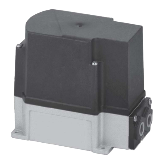
Introduction Product Description Product Features The Eclipse T500 Actuator is suitable for driving flow T500 Actuators designed optimize control valves, butterfly valves, dampers or other performance of a combustion system. Features include: applications which require rotary motion. • Power and approvals accepted globally •... -
Page 5: Safety
System Use terminal plugs. Protect against a electrical shock hazard by The Eclipse T500 Actuator must be used with an ensuring that the cover can be lifted upwards of approved listed combustion control system consisting of a the control unit, allowing safe setting of the cams flame safeguard and safety shut-off valves. - Page 6 EC directives and laws. In areas where DIN regulations apply, the mounting and installation must comply wth DIN/ VDE 0100, 0550 and DIN/VDE 0722. Eclipse T500 Actuator, V1, Instruction Manual 902, 12/7/2009...
-
Page 7: Installation
17. Some Quincy, MA 02269 models may have a square shaft. • Provide support for the weight of conduit or cables into the actuator. • Ensure clearance for cover removal. Eclipse T500 Actuator, V1, Instruction Manual 902, 12/7/2009... -
Page 8: Cam Adjustment
See Figure 3.2. When the shaft is rotated to align the slot • Make the electrical connections either temporary or to the pipe direction, the valve is at maximum flow. Eclipse as required by the application and apply power. BVs with the beveled shutter option have a 75 degree Verify for proper and smooth motion over the full stroke. -
Page 9: Shaft Disengage
Connect a 4-20mA signal positive (+) to X1-3 and negative (–) to X1-2 (GND). Or alternately connect a 0-10 Vdc signal positive (+) to X1-1 and negative (–) to X1-2 Figure 3.5. Actuator Wiring Eclipse T500 Actuator, V1, Instruction Manual 902, 12/7/2009... -
Page 10: Electrical Version, Range Adjustment
0° up to either 20° position (45°) for 12mA to 20mA. or 30°, depending on the upper limit adjustment. See Figure 3.7 for range and limits. Eclipse T500 Actuator, V1, Instruction Manual 902, 12/7/2009... -
Page 11: Connection Terminals
3 auxiliary switches and ORANGE one relay low/off BLUE high 5 4 3 1 2 * Only when driving from high position ign - ignition Figure 3.8. Connection Terminals (3-Position & 2-Position Step) Eclipse T500 Actuator, V1, Instruction Manual 902, 12/7/2009... - Page 12 X2-1, -2, or -4 then remove power at X2-5 Enable to avoid conflicting drive currents at the motor. SELV or PELV depends on the safety class of the connected devices. For PELV, the device is connected to protective earth (ground). Figure 3.9. Connection Terminals (Electronic Version) Eclipse T500 Actuator, V1, Instruction Manual 902, 12/7/2009...
-
Page 13: Cam Positions (Factory Settings)
Cam IV AUX switch 30-degree GREEN Cam VI AUX switch 30-degree Electronic Version Color Cam Position Presetting Cam I High-fire 90-degree BLACK Cam V Low-fire 10-degree GREEN Cam VI Off / Ignition 0-degree Eclipse T500 Actuator, V1, Instruction Manual 902, 12/7/2009... -
Page 14: Typical Application
NOTE: The following diagram is an example of how to use carefully. Make sure cover is seated properly to the actuator’s various inputs and outputs. Some devices seal out water. shown may be omitted or changed, depending on your application. Eclipse T500 Actuator, V1, Instruction Manual 902, 12/7/2009... -
Page 15: Specifications
<95% RH noncondensing Weight Approximately 2 kg Materials of Construction Housing Die Cast Aluminum Cover Impact-proof and heat resistant plastic At 60 Hz frequency, running times and torques are about 17% less. Eclipse T500 Actuator, V1, Instruction Manual 902, 12/7/2009... -
Page 16: Standards And Certificates
Suited for 105°C Potentiometer Range 0 to 135 , ± 5% Max. 1mm or AWG 12 Standards and Certificates Conformity of EEC directives: Electomagnetic compatibility EMC (immunity) 2004/108/EC Low voltage directive 2006/95/RC Eclipse T500 Actuator, V1, Instruction Manual 902, 12/7/2009... -
Page 17: Dimensions
Slot for woodruff key 3 x 3.7 DIN6888 Connecting cover Europe Connecting cover US 26.5 10.6 9.5 h11 Round Square (Standard) #8 - 32 0.6" deep Woodruff Key 0.39 (10) 0.12 0.44 (11.2) Figure 4.1. Eclipse T500 Actuator, V1, Instruction Manual 902, 12/7/2009... -
Page 18: Maintenance & Troubleshooting
Actuator stays at high Signal applied to drive high terminal Check external wiring and control system. Electronic Version: More than one Check external wiring and control analog signal applied to inputs system. Eclipse T500 Actuator, V1, Instruction Manual 902, 12/7/2009... - Page 19 NOTES Eclipse T500 Actuator, V1, Instruction Manual 902, 12/7/2009...
- Page 20 Offered By: Power Equipment Company 2011 Williamsburg Road Richmond, Virginia 23231 Phone (804) 236-3800 (804) 236-3882 www.peconet.com...


Need help?
Do you have a question about the TRILOGY T500 Series and is the answer not in the manual?
Questions and answers