Sign In
Upload
Manuals
Brands
Eclipse Manuals
Controller
UDC2500 Limit
Eclipse UDC2500 Limit Manuals
Manuals and User Guides for Eclipse UDC2500 Limit. We have
1
Eclipse UDC2500 Limit manual available for free PDF download: Manual
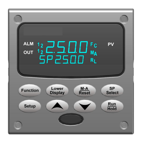
Eclipse UDC2500 Limit Manual (128 pages)
Eclipse Universal Digital Controller
Brand:
Eclipse
| Category:
Controller
| Size: 1.23 MB
Table of Contents
Table of Contents
4
Introduction
11
Overview
11
Figure 1-1 UDC2500 Operator Interface
12
Function of Keys
13
Process Instrument Explorer Software
14
Figure 1-2 Screen Capture of Process Instrument Explorer Running on a Pocket PC
14
Figure 1-3 Depiction of Infrared Communications
15
CE Conformity (Europe)
16
Installation
17
Overview
17
Condensed Specifications
18
Table 2-1 Condensed Specifications
18
Model Number Interpretation
21
Figure 2-1 Model Number Interpretation
22
Limit and Alarm Relay Contact Information
23
Table 2-2 Limit Relay Contact Information
23
Table 2-3 Alarm Relay Contact Information
23
Mounting
24
Figure 2-2 Mounting Dimensions (Not to Scale)
24
Table 2-4 Mounting Procedure
25
Figure 2-3 Mounting Method
25
Wiring
26
Electrical Considerations
26
Table 2-5 Permissible Wiring Bundling
27
Wiring Diagrams
28
Figure 2-4 Composite Wiring Diagram
28
Figure 2-5 Mains Power Supply
29
Figure 2-6 Input 1 Connections
30
Figure 2-7 Electromechanical Relay Output
31
Figure 2-8 Solid State Relay Output
31
Figure 2-9 Open Collector Output
32
Figure 2-10 RS-422/485 Communications Option Connections
32
Table 2-6 Terminals for Connecting a UDC to a MDI Compliant Hub or Switch
33
Table 2-7 Terminals for Connecting a UDC Directly to a PC Utilizing a Straight-Through Cable
33
Figure 2-11 Ethernet Communications Option Connections
33
Figure 2-12 Auxiliary Output and Digital Inputs Option Connections
34
Limit Control Application Diagram
35
Figure 2-14 Transmitter Power for 4-20 Ma - 2 Wire Transmitter Using Auxiliary Output
35
Figure 2-15 Limit Controller Application Diagram
35
Configuration
36
Overview
36
Table 3-1 Configuration Topics
36
Configuration Prompt Hierarchy
37
Table 3-2 Configuration Prompt Hierarchy
37
Configuration Procedure
38
Table 3-3 Configuration Procedure
38
Lock Set up Group
39
Table 3-4 LOCK Group Function Prompts
39
Limit Set up Group
40
Table 3-5 LIMIT Group Function Prompts
40
Input 1 Set up Group
41
Table 3-6 INPUT 1 Group Function Prompts
41
Options Set up Group
45
Table 3-7 OPTION Group Function Prompts
45
Communications Set up Group
47
Table 3-8 Communications Group Function Prompts
47
Alarms Set up Group
50
Table 3-9 ALARMS Group Function Prompts
50
Display Set up Group
54
Table 3-10 DISPLY Group Function Prompts
54
Configuration Record Sheet
55
Operating the Limit Controller
56
Overview
56
Operator Interface
57
Entering a Security Code
57
Figure 4-1 Operator Interface
57
Lockout Feature
58
Table 4-1 Procedure to Enter a Security Code
58
Monitoring Your Limit Controller
59
Table 4-2 Annunciators
59
Table 4-3 Error Messages
60
Operating Your Limit Controller
61
Table 4-4 Using Contact Input Option
63
Alarm Setpoints
64
Table 4-5 Procedure for Displaying Alarm Setpoints
64
Input Calibration
65
Overview
65
Minimum and Maximum Range Values
66
Table 5-1 Voltage, Milliamp and Resistance Equivalents for Input 1 Range Values
66
Preliminary Information
68
Table 5-2 Equipment Needed
68
Figure 5-1 Input 1 Wiring Terminals
68
Input 1 Set up Wiring
69
Table 5-3 Set up Wiring Procedure for Thermocouple Inputs Using an Ice Bath
69
Figure 5-2 Wiring Connections for Thermocouple Inputs Using an Ice Bath
69
Table 5-4 Set up Wiring Procedure for Thermocouple Inputs Using Thermocouple Source
70
Table 5-5 Set up Wiring Procedure for RTD Inputs
70
Figure 5-3 Wiring Connections for Thermocouple Inputs Using Thermocouple Source
70
Figure 5-4 Wiring Connections for RTD (Resistance Thermometer Device)
70
Table 5-6 Wiring Connections for Radiamatic, Thermocouple Differential, Millivolts or Volts
71
Figure 5-5 Wiring Connections for Radiamatic, Millivolts, Volts or Thermocouple Differential
71
Table 5-7 Set up Wiring Procedure for 0 to 10 Volts
72
Table 5-8 Set up Wiring Procedure for Milliampere Inputs
72
Figure 5-6 Wiring Connections for 0 to 10 Volts
72
Figure 5-7 Wiring Connections for 0 to 20 Ma or 4 to 20 Ma Inputs
72
Input 1 Calibration Procedure
73
Table 5-9 Input 1 Calibration Procedure
73
Restore Input Factory Calibration
74
Table 5-10 Restore Input Factory Calibration
75
Output Calibration
77
Overview
77
Auxiliary Output Calibration
77
Table 6-1 Set up Wiring Procedure for Auxiliary Output
78
Figure 6-1 Wiring Connections for Calibrating Auxiliary Output
78
Restore Output Factory Calibration
79
Table 6-2 Auxiliary Output Calibration Procedure
79
Table 6-3 Restore Factory Calibration
80
Troubleshooting/Service
81
Overview
81
Troubleshooting Aids
82
Table 7-1 Procedure for Identifying the Software Version
83
Power-Up Tests
84
Status Tests
84
Table 7-2 Procedure for Displaying the Status Test Results
84
Background Tests
85
Table 7-3 Background Tests
85
Controller Failure Symptoms
87
Table 7-4 Controller Failure Symptoms
87
Troubleshooting Procedures
88
Table 7-5 Troubleshooting Power Failure Symptoms
89
Table 7-6 Troubleshooting Latching Output Relay Failure
90
Table 7-7 Troubleshooting Alarm Relay Output Failure
90
Table 7-8 Troubleshooting a Keyboard Failure
91
Table 7-9 Troubleshooting a RS-485 Communications Failure
92
Table 7-10 Troubleshooting Auxiliary Output Failure
93
Restoring Factory Configuration
94
Table 7-11 Restoring Factory Configuration
94
Parts List
95
Exploded View
95
Figure 8-1 UDC2500 Exploded View
95
Table 8-1 Parts Identification
96
Table 8-2 Parts Not Shown
96
Removing the Chassis
97
Modbus Rtu Function Codes
98
Overview
98
General Information
98
Table 9-1 Integer Parameter Type
99
Table 9-2 Floating Point Parameter Type
99
Function Code 20 (14H) - Read Configuration Reference Data
100
Table 9-3 Register Address Format for Function Code 20
101
Read Configuration Examples
102
Function Code 21 (15H) - Write Configuration Reference Data
104
Table 9-4 Register Address Format for Function Code 21
105
Write Configuration Examples
106
Modbus Read, Write and Override Parameters Plus Exception Codes
107
Overview
107
Reading Control Data
109
Miscellaneous Read Onlys
109
Register Addresses for Read Onlys
109
Table 10-1 Control Data Parameters
109
Table 10-2 Miscellaneous Read Onlys
109
Configuration Parameters
110
Lock
110
Table 10-3 Set-Up Group Lock
110
Limit
111
Table 10-4 Set-Up Group Limit
111
Input 1
112
Table 10-5 Set-Up Group - Input 1
112
Options
114
Table 10-6 Set-Up Group - Options
114
Communications
115
Table 10-7 Set-Up Group - Communications
115
Alarms
116
Table 10-8 Set-Up Group - Alarms
116
Display
118
Table 10-9 Set-Up Group - Display
118
Modbus RTU Exception Codes
119
Table 10-10 Modbus RTU Data Layer Status Exception Codes
120
Ethernet Tcp/Ip
121
Overview
121
Further Information
122
Modbus RTU Serial Communications
122
Modbus Messaging on TCP/IP
122
How to Apply Digital Instrumentation in Severe Electrical Noise Environments
122
Index
123
Advertisement
Advertisement
Related Products
Eclipse UltraSatin shutters
Eclipse ES Series
Eclipse ES363
Eclipse ES363M
Eclipse ES365
Eclipse ES365M
Eclipse ES366
Eclipse ES366L
Eclipse ES366M
Eclipse ES368
Eclipse Categories
Car Receiver
Burner
Car Navigation system
Car Stereo System
Speakers
More Eclipse Manuals
Login
Sign In
OR
Sign in with Facebook
Sign in with Google
Upload manual
Upload from disk
Upload from URL