
Subscribe to Our Youtube Channel
Related Manuals for CH Hanson PALMGREEN 9683336


Summary of Contents for CH Hanson PALMGREEN 9683336
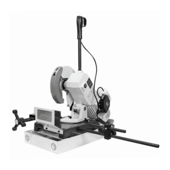
- Page 1 Operating Instructions & Parts Manual 9” Cold Saw 230 V, 1-Phase Model 9683336 9644292.01...
- Page 2 PLEASE READ AND SAVE THESE INSTRUCTIONS. READ CAREFULLY BEFORE ATTEMPTING TO ASSEMBLE, INSTALL, OPERATE OR MAINTAIN THE PRODUCT DESCRIBED. PROTECT YOURSELF AND OTHERS BY OBSERVING ALL SAFETY INFORMATION. FAILURE TO COMPLY WITH INSTRUCTIONS COULD RESULT IN PERSONAL INJURY AND/OR PROPERTY DAMAGE! RETAIN INSTRUCTIONS FOR FUTURE REFERENCE.
-
Page 3: Getting Started
GETTING STARTED or rubber components. After cleaning, cover all exposed surfaces with a light coating of oil. Save this manual Package Contents: You will need this manual for the safety warnings and Saw unit precautions, assembly instructions, operating and maintenance Trigger handle procedures, parts lists and diagrams. - Page 4 SAFETY RULES Preparing the work area for your job • Keep work area clean. Cluttered work areas invite accidents. Completely read and understand this owner’s manual before assembly or tool • Do not use power tools in dangerous environments. Do not operation.
-
Page 5: Specifications
Know how to use your tool SPECIFICATIONS The operation of any tool can result in The saw features a solid cast iron vise to ensure durability. The foreign objects being thrown into the eyes, which can result in severe eye damage. Always wear saw is equipped with a miter gauge for performing many different safety goggles complying with United States ANSI Z87.1. - Page 6 ASSEMBLY/INSTALLATION pallet. NOTE: The saw is heavy, see “SPECIFICATIONS”. Be certain Location any machine or devices used to lift the saw are capable The saw must be installed on a structurally stable surface. The of handling this weight. If manually lifting, ensure that coolant pump output and inputs may extend below the coolant enough people are performing the lift.
- Page 7 Assembly: Handle Depth stop Screw the shaft (item #22) into the top of the saw. Slide long bar stopper rod into bar stopper, and tighten the handle screw. Position and screw into the side of the blue base of the saw. Use provided nut to lock the bar stopper in the upright position.
-
Page 8: Operation
OPERATION Always wear safety glasses complying with U.S. ANSI Z87.1 before beginning any power tool operation. To avoid injury from unexpected starting, whenever changing the saw blade or carrying out adjustments, switch the saw off and remove the power cord from the mains outlet. To avoid injury to hands when handling the saw blade, wear gloves whenever necessary. -
Page 9: Blade Selection
BLADE SELECTION NOTE: Best performance of worm screw worm wheel gearing is guaranteed when circular saw blades with drawing-holes are used. Cutting Capcity (values in parentheses are in mm) 90º 1.18” (30) 2.56” (65) 2.17” x 2.17” (55 x 55) 1.77”... -
Page 10: Troubleshooting Guide
TROUBLESHOOTING GUIDE Symptom Possible Cause(s) Corrective Action Teeth breaking Coolant flow problem Ensure proper coolant flow; hoses unclogged; nozzles pointed correctly, etc. Make sure coolant type is suitable for the machine. Material too hard Check the blade speed and the type of blade you are using. Also be aware of feed pressure. - Page 11 Symptom Possible Cause(s) Corrective Action Motor will not turn Emergency stop engaged Rotate Emergency Stop button to disengage. Electrical power supply Check: the phases; the cables; the plug; the socket. Also check that the motor connections are in place. Trigger switch not activating Check that socket/plug connection from handle to motor is inserted correctly;...
-
Page 12: Maintenance/Repair
MAINTENANCE/REPAIR Replacement of gear box oil • Remove caps 38 and 19, let all the used oil flow out into a container which should have a label indicating the contents for the purposes of disposal. • Replace cap 19. Feed 0.2 litres of oil (as specified above) into the oil feed hole located on the upper part of the gear box and then replace cap 38. - Page 14 POS. DESCRIPTION Part POS. DESCRIPTION Part Number Number Snap Ring ?9 E Dowel M8x35 DIN-914 UNI- 9644258.01 5927 Bench 9644230.01 Switch box 9644259.01 Bearing 629-2RS ?9/26x8 Not shown Pin 8x26 DIN-6325 9644231.01 Motor M80 V230/50 1F 4P 9644261.01 Not shown B4 HP1 Vice screw 9644233.01...
- Page 15 POS. DESCRIPTION Part Number Fan MEC80 9644284.01 ”Self Locking Ring Nut M25x1 5” ”Belleville Washer 16x8 2x2 DIN-2093” Bush ?6 9644285.01 HSFHC screw M4x8 DIN- 7991 Electrical cable 2x1 9644286.01 ”RH screw M2 9x13 DIN- 7981” Micro switch of handle 9644287.01 Capacitor 25æFñ5% SH 9644288.01...
- Page 16 PALMGREN WARRANTY C.H. Hanson / Palmgren warrants their products to be free of defects in material or workmanship. This warranty does not cover defects due directly or indirectly to misuse, abuse, normal wear and tear, failure to properly maintain the product, heated, ground or otherwise altered, or used for a purpose other than that for which is was intended.
Need help?
Do you have a question about the PALMGREEN 9683336 and is the answer not in the manual?
Questions and answers