
Related Manuals for CH Hanson Palmgren 9683337


Summary of Contents for CH Hanson Palmgren 9683337
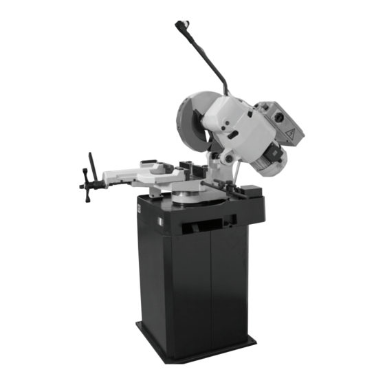
- Page 1 Operating Instructions & Parts Manual 14” Cold Saw 230 V, 3-Phase Model 9683337 9644410.01...
- Page 2 PLEASE READ AND SAVE THESE INSTRUCTIONS. READ CAREFULLY BEFORE ATTEMPTING TO ASSEMBLE, INSTALL, OPERATE OR MAINTAIN THE PRODUCT DESCRIBED. PROTECT YOURSELF AND OTHERS BY OBSERVING ALL SAFETY INFORMATION. FAILURE TO COMPLY WITH INSTRUCTIONS COULD RESULT IN PERSONAL INJURY AND/OR PROPERTY DAMAGE! RETAIN INSTRUCTIONS FOR FUTURE REFERENCE.
-
Page 3: Getting Started
GETTING STARTED or rubber components. After cleaning, cover all exposed surfaces with a light coating of oil. Save this manual Package Contents: You will need this manual for the safety warnings and Saw unit precautions, assembly instructions, operating and maintenance Base/stand procedures, parts lists and diagrams. - Page 4 SAFETY RULES Preparing the work area for your job • Keep work area clean. Cluttered work areas invite accidents. Completely read and understand this owner’s manual before assembly or tool • Do not use power tools in dangerous environments. Do not operation.
-
Page 5: Specifications
Know how to use your tool SPECIFICATIONS The operation of any tool can result in The saw features a solid cast iron vise to ensure durability. The foreign objects being thrown into the eyes, which can result in severe eye damage. Always wear saw is equipped with a miter gauge for performing many different safety goggles complying with United States ANSI Z87.1. - Page 6 ASSEMBLY/INSTALLATION Lifting and setting up the saw Make certain that slings, cables, chains, Location forklifts or other load suspending gear or machines used to move this saw are properly rated to The saw must be installed on a structurally stable surface. handle the weight.
- Page 7 Carefully lift the saw off the pallet. Lift it no higher than necessary to clear the surface on which it is to be installed and pull the pallet out of the way. DO NOT put your hands or feet beneath the saw while moving it or removing the pallet. Place the saw into its final location.
-
Page 8: Operation
OPERATION Without touching the micro switch, verify that the material to be cut is positioned as required by lowering the blade to the Always wear safety glasses complying material. If everything is properly set, return to start position, with U.S. ANSI Z87.1 before beginning any otherwise adjust as required. -
Page 9: Changing Blades
CHANGING BLADES To remove and replace the saw blade: Make sure the cold saw is disconnected from the power. Hold the saw blade still, by lowering the blade into a piece of wood set in the vise. Unhook the guard rod (A) from the guard. Blade Housing Blade Guard... -
Page 10: Blade Selection
BLADE SELECTION NOTE: Best performance of worm screw worm wheel gearing is guaranteed when circular saw blades with drawing-holes are used. Cutting Capcity (values in parentheses are in mm) 90º 1.18” (30) 2.56” (65) 2.17” x 2.17” (55 x 55) 1.77”... -
Page 11: Troubleshooting Guide
TROUBLESHOOTING GUIDE Symptom Possible Cause(s) Corrective Action Teeth breaking Coolant flow problem Ensure proper coolant flow; hoses unclogged; nozzles pointed correctly, etc. Make sure coolant type is suitable for the saw. Material too hard Check the blade speed and the type of blade you are using. Also be aware of feed pressure. - Page 12 Symptom Possible Cause(s) Corrective Action Motor will not turn Emergency stop engaged Rotate Emergency Stop button to disengage. Electrical power supply Check: the phases; the cables; the plug; the socket. Also check that the motor connections are in place. Trigger switch not activating Check that socket/plug connection from handle to motor is inserted correctly;...
-
Page 13: Maintenance/Repair
MAINTENANCE/REPAIR Replacement of gear box oil Place a container, labeled to indicate the contents for the purposes of disposal, beneath cap 22. Remove caps 95 and 22 (see “Parts List” on page 14), and let the used oil drain into the container . - Page 14 Parts List...
- Page 19 POS. DESCRIPTION Part number POS. DESCRIPTION Part number Pedestal 9644327.01 Base O-Ring 134 9644328.01 Rotating arm 9644329.01 Roller arm pin 9644330.01 Hexagon lock nut M20 DIN- Snap ring ø25 DIN-471 Nut M10 DIN-934 Screw HH M10x55 DIN-934 Electric pump 9644354.01 Roller arm 9644331.01 Roller...
- Page 20 POS. DESCRIPTION Part POS. DESCRIPTION Part number number Stake ø9x18 9644385.01 Selflocking ring nut M32x1.5 Vice bush 9644386.01 Key 10x8x28 DIN-6604 Grub screw M10x50 Disk shaft 9644366.01 Washer for M10 Oil retainer 50/65x8 9644367.01 Self locking nut M10 Oil filling cap ø3/8” 9644368.01 Nut M10 DIN-934 Left vice jaw...
- Page 22 PALMGREN WARRANTY C.H. Hanson / Palmgren warrants their products to be free of defects in material or workmanship. This warranty does not cover defects due directly or indirectly to misuse, abuse, normal wear and tear, failure to properly maintain the product, heated, ground or otherwise altered, or used for a purpose other than that for which is was intended.
Need help?
Do you have a question about the Palmgren 9683337 and is the answer not in the manual?
Questions and answers