Advertisement
Quick Links
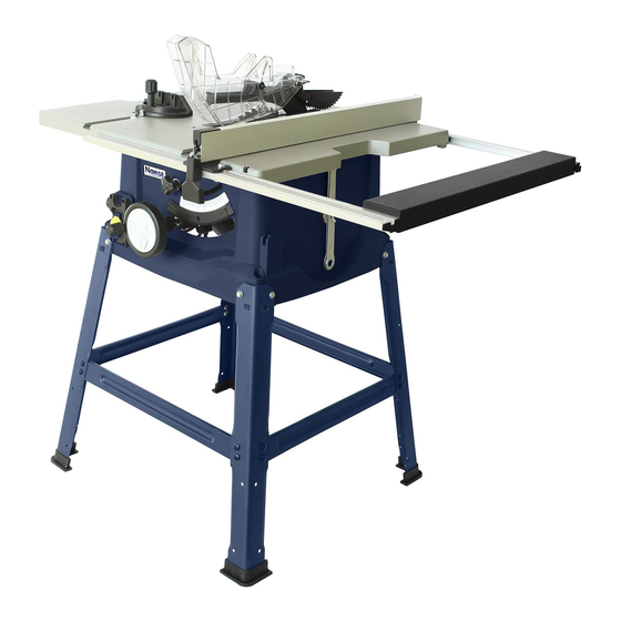
Operating Instructions & Parts Manual
Model 9683412
10˝
Table Saw
Please read and save these instructions. Read carefully before attempting to
assemble, install, operate or maintain the product described.
Protect yourself and others by observing all safety information. Failure to comply
with instructions could result in personal injury and/or property damage!
Retain instructions for future reference.
9643342.01 0518
Advertisement

Related Manuals for CH Hanson NORSE 9683412


Summary of Contents for CH Hanson NORSE 9683412
- Page 1 Operating Instructions & Parts Manual Model 9683412 10˝ Table Saw Please read and save these instructions. Read carefully before attempting to assemble, install, operate or maintain the product described. Protect yourself and others by observing all safety information. Failure to comply with instructions could result in personal injury and/or property damage! Retain instructions for future reference.
- Page 2 TABLE OF CONTENTS SAFETY GUIDELINES ..........2-7 FEATURES .
- Page 3 SAFETY GUIDELINES • DON’T FORCE TOOL. • USE RIGHT TOOL. • USE THE PROPER EXTENSION CORD. • DRESS PROPERLY. • ALWAYS WEAR SAFETY GLASSES WITH SIDE SHIELDS. • SECURE WORK. • DON’T OVERREACH. • MAINTAIN TOOLS WITH CARE. • DISCONNECT TOOLS. •...
- Page 4 SAFETY GUIDELINES • WHEN OPERATING A POWER TOOL OUTSIDE, USE AN OUTDOOR EXTENSION CORD MARKED “W-A” OR “W”. These cords are rated for outdoor use and reduce the risk of electric shock. • KEEP BLADES CLEAN, SHARP, AND WITH SUFFICIENT SET. Sharp blades minimize stalling and kickback.
- Page 5 SAFETY GUIDELINES • IF THE POWER SUPPLY CORD IS DAMAGED, • AVOID AWKWARD OPERATIONS AND HAND POSITIONS where a sudden slip • USE ONLY RECOMMENDED ACCESSORIES listed in this manual or addendums. Instructions for safe use of accessories are included with the accessory. •...
- Page 6 ELECTRICAL All electrical connections must be performed by a qualified electrician. Power Source Connect sander to a supply circuit protected by a circuit breaker or time-delay fuse. The motor is designed for operation on the voltage and frequency specified. Normal loads will be handled safely on voltages not more than 10% above or below the specified voltage.
- Page 7 This work should be performed by a qualified electrician. A temporary 3-prong to 2-prong Grounding Lug Make sure this is grounding adapter is available for Adapter connected to a connecting plugs to a two pole outlet if known grounded it is properly grounded. 3-Prong Plug receptacle.
- Page 8 FEATURES ANTI- BLADE KICKBACK GUARD PAWLS KNOW YOUR TABLE SAW MITER RIP FENCE GAUGE See Figure 2. The safe use of this product requires an understanding of the information on the tool and in this operator’s manual, as well as a knowledge SCALE of the project you are attempting.
- Page 9 FEATURES SWITCH ASSEMBLY SWITCH SWITCH See Figure 3. SWITCH KEY feature. This feature SWITCH IN LOCKED POSITION Fig. 3 TO TURN YOUR SAW ON: TO TURN YOUR SAW OFF: TO LOCK YOUR SAW: • Press the switch down. WARNING! WARNING! WARNING! BLADES WARNING!
- Page 10 TABLE OF CONTENTS ASSEMBLY AND ADJUSTMENTS SAFETY GUIDELINES ..........2-7 FEATURES .
- Page 11 ASSEMBLY AND ADJUSTMENTS LOOSE PARTS UNPACKING The following items are included with the table saw leg stand: NOTE: needed. WARNING! if any parts on the Loose Parts Lists are your product when you customer installation. Use of a product that may Fig.
- Page 12 TABLE OF CONTENTS ASSEMBLY AND ADJUSTMENTS SAFETY GUIDELINES ..........2-7 WARNING! Never stand directly in line with the blade or allow hands to come closer than 3 in.
- Page 13 ASSEMBLY AND ADJUSTMENTS TO INSTALL THE HANDLE See Figure 9. • Hold the nylon nut securely and turn the screw counterclockwise to remove the nut completely. NOTE: Do not remove the screw from the handle. • Place the nylon nut into the recessed hole on the back of the height/bevel adjusting handwheel and hold in place.
- Page 14 TABLE OF CONTENTS ASSEMBLY AND ADJUSTMENTS TO CHANGE RIVING KNIFE POSITIONS SAFETY GUIDELINES ..........2-7 FEATURES .
- Page 15 ASSEMBLY AND ADJUSTMENTS TO CHECK SAW BLADE INSTALLATION NOTICE: Fig. 12 To loosen the blade: pull the closed end wrench forward to the front of the machine. To tighten the blade:...
- Page 16 ASSEMBLY AND ADJUSTMENTS TO INSTALL THE BLADE GUARD AND ANTI-KICKBACK PAWLS WARNING! BLADE GUARD GUARD LEVER To install anti-kickback pawls: Fig. 13 PAWL HANDLE BUTTON NOTE: ANTI-KICKBACK PAWLS TO INSTALL THE BLADE GUARD: Fig. 14 position. CORRECT NOTE: INCORRECT Fig. 15...
- Page 17 ASSEMBLY AND ADJUSTMENTS TO CHECK AND ALIGN THE RIVING KNIFE AND RIVING SAW BLADE KNIFE FRAMING SQUARE To check alignment of the riving knife: Fig. 16 HORIZON TAL ADJUSTMENT RIVING FRAMING KNIFE SQUARE NOTE: BLADE VERTICAL ADJUSTMENT RIVING FRAMING KNIFE SQUARE To adjust (horizontally and vertically): BLADE...
- Page 18 ASSEMBLY AND ADJUSTMENTS OPERATIONS TO CHANGE RIVING KNIFE POSITIONS WARNING! RELEASE LEVER (UNLOCKED) WARNING! operations. WARNING! To place in the “up” position for all this tool. The use of attachments or accessories not recommended can result in serious through cutting: WARNING! IN “UP”...
- Page 19 OPERATIONS AVOIDING KICKBACK fence. CUTTING AIDS NOTICE:...
- Page 20 OPERATIONS TYPE OF CUTS CROSS CUT WARNING! RIP CUT MITER CUT Fig. 24 WARNING!
- Page 21 OPERATIONS TO CHANGE BLADE DEPTH BEVEL CROSS CUT BEVEL RIP CUT TO CHANGE BLADE ANGLE (BEVEL) COMPOUND (BEVEL) MITER CUT Fig. 25 NOTE: GULLET Fig. 26...
- Page 22 OPERATIONS 45º ADJUSTMENT 90º ADJUSTMENT SCREW SCREW BEVEL LOCKING LEVER WARNING! HEIGHT/BEVEL ADJUSTING HANDWHEEL sure the rip fence is operation. TO DECREASE TO INCREASE ANGLE ANGLE TO USE THE RIP FENCE Fig. 27 unit. process. NOTE: FENCE CLAMP BLADE SCREW SCALE LOCKING LEVER...
- Page 23 OPERATIONS TO SET THE RIP FENCE SCALE INDICATOR TO THE BLADE NOTE: TO USE THE MITER GAUGE and your hands. MITER LOCK GAUGE BODY KNOB on the scale. MITER GAUGE Fig. 30...
- Page 24 OPERATIONS WARNING! reset. HEELING (PARALLELING) THE BLADE TO THE MITER GAUGE GROOVE RIGHT MITER COMBINATION GAUGE GROOVE SQUARE Fig. 31 COMBINATION SQUARE Fig. 32 NOTE: BLADE TOO CLOSE TO MITER GAUGE GROOVE Fig. 33 WARNING!
- Page 25 BLADE ADJUSTMENTS BLADE ADJUSTMENTS WARNING! TO REPLACE THE BLADE pawls. Fig. 43 BLADE BLADE ARBOR WASHER SHAFT BLADE washer. Fig. 44 TABLE RIVING INSERT KNIFE To install a standard blade: BLADE must point down toward the front of the saw to Fig.
- Page 26 BLADE ADJUSTMENTS TO SET THE BLADE AT 0° AND 45° See Figures 46 - 48. 45° ADJUSTMENT 45° ADJUSTMENT 0° ADJUSTMENT 0° ADJUSTMENT The angle settings of the saw have been SCREW SCREW SCREW SCREW set at the factory and, unless damaged in shipping, should not require setting during assembly.
- Page 27 BLADE ADJUSTMENTS BLADE ADJUSTMENTS TO CHECK THE ALIGNMENT FRAMING OF THE RIP FENCE TO THE BLADE FENCE SQUARE BLADE BOLTS LOCKING Fig. 49 LEVER side. process. MAINTENANCE WARNING! WARNING! WARNING! GENERAL MAINTENANCE WARNING!
- Page 28 MAINTENANCE MAINTENANCE LUBRICATION TROUBLESHOOTING PROBLEM CAUSE SOLUTION Saw is not mounted securely. Blade is warped Rip fence not mounted Remount the smoothly. correctly. rip fence. Blade is dull. Operations section. Slow the feed rate. Wood is warped. Replace the wood. Always surface.
- Page 29 MAINTENANCE MAINTENANCE TROUBLESHOOTING PROBLEM CAUSE SOLUTION handwheel is hard to turn. dust. Saw does not start. Motor cord or wall cord not Replace circuit fuse. replaced at your nearest Blade is dull or dirty. Replace with correct type. Blade does not lower when position.
- Page 30 PARTS ILLUSTRATION...
- Page 31 PARTS LIST Ref. Ref. Ref. No. Description Part No. Qty. No. Description Part No. Qty. No. Description Part No. Qty. Table insert 9643343.01 Self tapping screws 205 Upper guard lever 9643409.01 Screw M6 X 40 M4 x 20 206 Label 9643410.01 Table 9643344.01...
- Page 32 NORSE Warranty NORSE by C.H. Hanson warrants their products to be free of defects in material or workmanship. This warranty does not cover defects due directly or indirectly to misuse, abuse, normal wear and tear, failure to properly maintain the product, heated, ground or otherwise altered, or used for a purpose other than that for which it was intended.
Need help?
Do you have a question about the NORSE 9683412 and is the answer not in the manual?
Questions and answers