Table of Contents
Advertisement
Quick Links
Advertisement
Table of Contents

Related Manuals for Pilz PNOZ 8


Summary of Contents for Pilz PNOZ 8
- Page 1 PNOZ 8 Safety relays Operating Manual-22152-EN-05...
- Page 2 Preface This document is the original document. All rights to this documentation are reserved by Pilz GmbH & Co. KG. Copies may be made for the user's internal purposes. Suggestions and comments for improving this documenta- tion will be gratefully received.
-
Page 3: Table Of Contents
Operation ..........................Status indicators ........................Faults – Interference ......................Dimensions in mm ......................... Technical details ........................Safety characteristic data ......................Supplementary data ......................Service life graph ........................Order reference ........................EC declaration of conformity ....................Operating Manual PNOZ 8 22152-EN-05... -
Page 4: Introduction
PNOZ 8 Introduction Validity of documentation This documentation is valid for the product PNOZ 8. It is valid until new documentation is published. This operating manual explains the function and operation, describes the installation and provides guidelines on how to connect the product. -
Page 5: Safety
This gives advice on applications and provides information on special fea- tures. Safety Intended use The safety relay PNOZ 8 provides a safety-related interruption of a safety circuit. The safety relay meets the requirements of EN 60947-5-1 and EN 60204-1 and may be used in applications with: E-STOP pushbuttons... -
Page 6: Use Of Qualified Personnel
Note for overvoltage category III: If voltages higher than low voltage (>50 VAC or >120 VDC) are present on the unit, connected control elements and sensors must have a rated insulation voltage of at least 250 V. Operating Manual PNOZ 8 22152-EN-05... -
Page 7: Unit Features
The circuit is redundant with built-in self-monitoring. The safety function remains effective in the case of a component failure. The correct opening and closing of the safety function relays is tested automatically in each on-off cycle. Operating Manual PNOZ 8 22152-EN-05... -
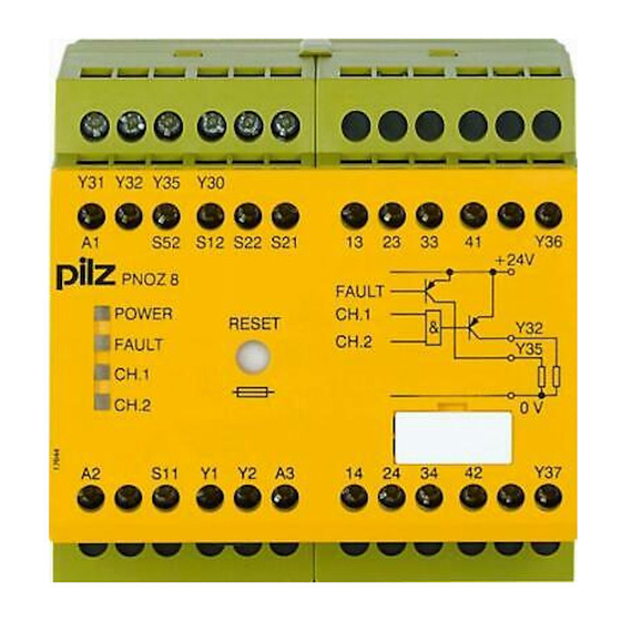
Page 8: Block Diagram/Terminal Configuration
III), Protective separation (overvoltage category II) Type: DC : 24 VDC; Order no. 774760 A1 A2 Feed- back/ Start *Insulation between the non-marked area and the relay contacts: Basic insulation (over- voltage category III), Protective separation (overvoltage category II) Operating Manual PNOZ 8 22152-EN-05... -
Page 9: Function Description
PNOZ 8 Function Description The safety relay PNOZ 8 provides a safety-oriented interruption of a safety circuit. When supply voltage is supplied the "POWER" LED is lit. The unit is ready for operation when the feedback loop Y1-Y2 and the start circuit S12-Y1 are closed. -
Page 10: Timing Diagram
Use the notch on the rear of the unit to attach it to a DIN rail (35 mm). When installed vertically: Secure the unit by using a fixing element (e.g. retaining bracket or end angle). Operating Manual PNOZ 8 | 10 22152-EN-05... -
Page 11: Wiring
Important for detection of shorts across contacts: As this function for detecting shorts across contacts is not failsafe, it is tested by Pilz during the final control check. If there is a danger of exceeding the cable runs, we recommend the following test after the installation of the device: 1. -
Page 12: Preparing For Operation
Safety gate with detection of shorts across contacts NOTICE With single-channel wiring the safety level of your machine/plant may be lower than the safety level of the unit (see Safety characteristic data [ 21]). Operating Manual PNOZ 8 | 12 22152-EN-05... - Page 13 The unit starts up automatically when the safeguard is reset, e.g. when the E-STOP pushbutton is released. Use external circuit measures to prevent an unexpected restart. Feedback loop with feedback loop monitoring without feedback loop monitoring Link or contacts from external contactors Operating Manual PNOZ 8 | 13 22152-EN-05...
-
Page 14: Operation
SIL CL 2/PL d at least 1x per year NOTICE The safety function should be checked after initial commissioning and each time the plant/machine is changed. The safety functions may only be checked by qualified personnel. Operating Manual PNOZ 8 | 14 22152-EN-05... -
Page 15: Status Indicators
Contact malfunctions: If the contacts have welded, reactivation will not be possible after the input circuit has opened. LED "POWER" does not light: Short circuit or no supply voltage. Dimensions in mm 75 (2.95") 90 (3.54") 87 (3.42") Operating Manual PNOZ 8 | 15 22152-EN-05... -
Page 16: Technical Details
Current 50 mA 50 mA External supply voltage 24 V 24 V Voltage tolerance -20 %/+20 % -20 %/+20 % Residual current at "0" signal 0,1 mA 0,1 mA Max. internal voltage drop Operating Manual PNOZ 8 | 16 22152-EN-05... - Page 17 In accordance with the standard EN 60947-5-1 EN 60947-5-1 Utilisation category of safety con- tacts AC15 at 230 V 230 V Max. current DC13 (6 cycles/min) at 24 V 24 V Max. current Operating Manual PNOZ 8 | 17 22152-EN-05...
- Page 18 Ith per contact at UB AC; AC1: 240 V, DC1: 24 V Conv. therm. current with 1 con- tact – Conv. therm. current with 2 con- tacts – Conv. therm. current with 3 con- tacts – Operating Manual PNOZ 8 | 18 22152-EN-05...
- Page 19 In accordance with the standard EN 60947-1 EN 60947-1 Overvoltage category III / II III / II Pollution degree Rated insulation voltage 250 V 250 V Rated impulse withstand voltage 4 kV 4 kV Operating Manual PNOZ 8 | 19 22152-EN-05...
- Page 20 8 mm Dimensions Height 87 mm 87 mm Width 90 mm 90 mm Depth 121 mm 121 mm Weight 450 g 600 g Where standards are undated, the 2020-07 latest editions shall apply. Operating Manual PNOZ 8 | 20 22152-EN-05...
-
Page 21: Safety Characteristic Data
If the service life graphs are not accessible, the stated PFH value can be used irrespective of the switch frequency and the load, as the PFH value already considers the relay's B10d value as well as the failure rates of the other components. Operating Manual PNOZ 8 | 21 22152-EN-05... -
Page 22: Service Life Graph
With capacitive loads, any power surges that occur must be noted. With DC con- tactors, use flywheel diodes for spark suppression. Order reference Product type Features Connection type Order no. PNOZ 8 24 V DC Screw terminals 774760 PNOZ 8 230 VAC Screw terminals 774768 Operating Manual PNOZ 8 | 22 22152-EN-05... -
Page 23: Ec Declaration Of Conformity
European Parliament and of the Council. The complete EC Declaration of Conformity is available on the Internet at www.pilz.com/support/downloads. Representative: Norbert Fröhlich, Pilz GmbH & Co. KG, Felix-Wankel-Str. 2, 73760 Ost- fildern, Germany Operating Manual PNOZ 8... - Page 24 We are represented internationally. Please refer to our homepage www.pilz.com for further details or contact our headquarters. Headquarters: Pilz GmbH & Co. KG, Felix-Wankel-Straße 2, 73760 Ostfildern, Germany Telephone: +49 711 3409-0, Telefax: +49 711 3409-133, E-Mail: info@pilz.com, Internet: www.pilz.com...
Need help?
Do you have a question about the PNOZ 8 and is the answer not in the manual?
Questions and answers