Table of Contents
Advertisement
Quick Links
DATASHEET AND INSTALLATION MANUAL
DESCRIPTION
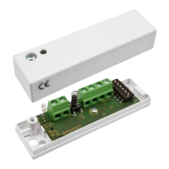
CD 470 offers reliable monitoring against attacks with
mechanical tools. The CD 470 is a chock- and vibration
detector with 3 separate detection channels: an integra-
tion channel / saw channel for weak signals with long
duration, a counting channel that senses strong impact
on the monitored surface and an explosion channel
which senses very strong signals from e.g. an explosion.
CD 470 shares design with CD 475 but has built-in relays
for the alarm and tamper outputs. This allows the CD 470
to be connected directly to the alarm central unit, this
means that no analyser unit is necessary.
CD 470-I has the same functionality as CD 470, but is also
equipped with back tamper and PC interface.
CD 470 is polarity independent, just like CD 475.
FEATURES
Relay outputs for alarm and tamper
Polarity independent for easy connection
3 separate detection channels
Cover radius up to 3m
Resistant to interference
Detailed sensitivity setting
Suitable for 24-hour monitoring
DAY and NIGHT control of LED
© 2020 Alarmtech
www.alarmtech.se
DETECTORS
Alarmtech reserves the right to changes
Shock- and vibration detector
OPERATING PRINCIPLE
The CD 470 uses a piezoelectric sensor to monitor the vibration
signature of the mounting surface that occurs when it is
crushed or cut with tools. The signal has a special signature
with a broad spectrum and high amplitude that the electronics
detects, then opens the alarm relay and illuminates the LED.
The CD 470 has a built-in self-control and voltage monitoring.
Fault is indicated by a flashing LED (alarm relay remains closed).
The indication is controlled by a DAY and NIGHT function. With
8Vdc on the power input, DAY mode is active and LED lights up
at alarm and with pulsating shine in case of failure. At 6Vdc,
NIGHT mode is active and LED is switched off in case of alarm
or fault.
Resetting the detector after alarm can be done in two different
ways:
Disconnect power to the detector
Switch from DAY to NIGHT mode
MOUNTING
1.
Loosen the screw for the cover and lift it off.
2.
Select the mounting location and mark the mounting holes
with the bottom part as a template.
3.
Drill with a 2-2.5 mm drill for the two supplied mounting
screws.
NOTE! A clean and smooth mounting surface under the
detector provides maximum range.
CONNECTIONS
The detector has 6 screw terminals:
#
Function
1
DC Input voltage (-) or (+)
2
DC Input voltage (-) or (+)
3
Alarm output, relay (NC)
4
Alarm output, relay (C)
5
Tamper output, relay (NC)
6
Tamper output, relay (C)
CD470 manual 2013en
CD 470
Page 1 of 2
Advertisement
Table of Contents

Related Manuals for Alarmtech CD 470-I


Summary of Contents for Alarmtech CD 470-I
- Page 1 Select the mounting location and mark the mounting holes CD 470-I has the same functionality as CD 470, but is also with the bottom part as a template. Drill with a 2-2.5 mm drill for the two supplied mounting equipped with back tamper and PC interface.
- Page 2 EN 50131-2-8 Grade 2, SBSC Klass 2, VdS Klasse B ORDERING INFORMATION CD 470 E nr. 63 098 91 CD 470-I – CD 470 with back tamper and PC- connection E nr. 63 099 92 Mounting plate MP 550 E nr. 63 098 93 ©...
Need help?
Do you have a question about the CD 470-I and is the answer not in the manual?
Questions and answers