Advertisement
Quick Links
CD 400 Instruction Manual
Detectors
Instruction Manual
DESCRIPTION
The CD 400 is a selectively sensing piezoelectric sensor that
detects and analyses the vibrations generated by the
attempts of an intruder to penetrate the protected area. The
highly sophisticated signal processing evaluates the
amplitude, frequency and duration of the vibrations
generated. The unit can be mounted on any stable surface
where an intrusion attempt might occur. However, the
following must be taken in to account:
1. The design and construction of the protected surface and
its material.
2. The detector location in relation to studs, joints,
door/windows hinges etc.
3. Background disturbances that can influence the detector.
COVERAGE
The typical coverage in various materials is shown in the
table below. The ranges
are only presented as guidelines,
practical tests must always be conducted.
Material
Steel/Wood/Glass
Range
r = 3 m
MOUNTING
1. Loosen the cover screws and remove it.
2. Select a suitable mounting position.
3. Use the bottom part as a template and mark the foxing
holes.
4. Use a 2-2.5 mm drill for the self-tapping screws provided.
Note! A clean and even surface under the detector will give
the beat coverage.
© 2018 Alarmtech
Brick/Plaster
Concrete
r = 2 m
r =1 m
www.alarmtech.se
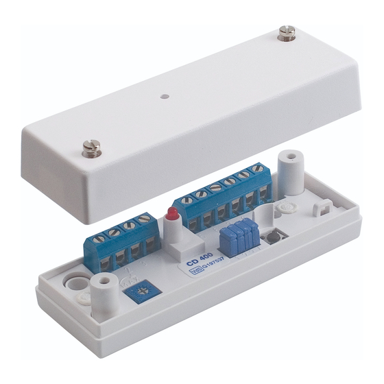
CONNECTION
The detector has 10 screw terminals with wire guard as
shown in Figure 1. The figure also shows the position of the
programming jumpers. A connection and programming
diagram is also filled inside the cover.
Note! Open inputs 3 & 4 are interpreted as low.
Figure 1. Connections to CD 400
PROGRAMMING JUMPERS
The four jumpers are used to programme the operational
modes of the detector. The functions are shown in Figure 2.
and also inside the cover.
S1 and S2 control the number of pulses to activate the alarm
relay.
S3 controls the alarm relay according to the following:
A) latched after activation, requiring a remote reset or
B) automatic reset after 2 seconds.
S4 controls the remote control and "DAY/NIGHT" functions.
On delivery all 4 jumpers are closed resulting in the
following:
S1, 2 - Reacts to a single impact (pulse).
S3 - The alarm relay is automatically reset after 2 seconds.
S4 - LED indicating an alarm activation.
Figure 2. Jumper functions
4-CD400-01
Shock detector
CD 400
Rev. CD 400_1845en
Advertisement

Subscribe to Our Youtube Channel
Related Manuals for Alarmtech CD 400


Summary of Contents for Alarmtech CD 400
- Page 1 Note! Open inputs 3 & 4 are interpreted as low. DESCRIPTION The CD 400 is a selectively sensing piezoelectric sensor that detects and analyses the vibrations generated by the attempts of an intruder to penetrate the protected area. The highly sophisticated signal processing evaluates the Figure 1.
- Page 2 CD 400 Instruction Manual 4-CD400-01 REMOTE DAY/NIGHT CONTROL See Figures 3 and 4. Max 15 detectors. ADJUSTMENT AND SETTING-UP NOTE! Jumper 4 must be open (removed) Adjusting and setting is quite simple. Check that jumper 4 is Figure 4A shows DAY/NIGHT control with terminal 4, an closed.
Need help?
Do you have a question about the CD 400 and is the answer not in the manual?
Questions and answers