ABB FEN-01 User Manual
Ttl encoder interface
Hide thumbs
Also See for FEN-01:
- User manual (32 pages) ,
- Quick manual (18 pages) ,
- Quick manual (16 pages)

Related Manuals for ABB FEN-01


Summary of Contents for ABB FEN-01
- Page 1 — OPTIONS FOR ABB DRIVES AND CONVERTERS TTL Encoder Interface FEN-01 User's manual...
- Page 3 TTL Encoder Interface FEN-01 User's manual Table of contents 3AFE68784603 Rev E Original instructions EFFECTIVE: 2023-07-14...
-
Page 5: Table Of Contents
The FEN-01 TTL Encoder Interface ........ - Page 6 6 Table of contents Dimensions ..................General .
-
Page 7: Safety Instructions
Overview This chapter states the general safety instructions that must be followed when installing and operating the FEN-01. In addition to the safety instructions given below, read the complete safety instructions of the specific drive you are working on. - Page 8 8 Safety instructions The motor cable terminals of the drive are at a dangerously high voltage when mains power is applied, regardless of motor operation. There can be dangerous voltages inside the drive from external control circuits even when the drive mains power is shut off. Exercise appropriate care when working on the unit.
-
Page 9: Introduction
Intended audience The manual is intended for the people who are responsible for commissioning and using the FEN-01. The reader is expected to have a basic knowledge of electrical fundamentals, electrical wiring practices and how to operate the drive. Before you start It is assumed that the drive is installed and the drive power supply is switched off before starting the installation of the extension module. -
Page 11: Hardware Description
Hardware description 11 Hardware description Contents of this chapter This chapter contains a short description of the FEN-01 TTL Encoder Interface module. -
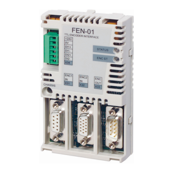
Page 12: The Fen-01 Ttl Encoder Interface
12 Hardware description The FEN-01 TTL Encoder Interface The FEN-01 offers an interface for two TTL encoder connections, one with commutation signals and PTC support. It also offers a TTL encoder output for emulation purposes and two digital latch inputs for position latching. -
Page 13: Fen-01 Connections
Hardware description 13 FEN-01 connections ■ The following figure shows an overview of the connections of the FEN-01. ACSXXX ACSXXX FEN-01 Sensor (optional) Encoder... -
Page 14: Isolation Areas
The shields of sockets X31 and X32 and plug X33 are connected to chassis. The fixing screw connects the chassis to ground. Compatibility FEN-01 is compatible with the following encoders. • TTL incremental encoder, 1...65535 pulses/rev, supports reference mark •... -
Page 15: Installation
Installation 15 Installation Contents of this chapter This chapter contains instructions on installing the TTL Encoder Interface module. WARNING! Follow the safety instructions given in this guide and in the drive's hardware manual. -
Page 16: Setting The Supply Voltage
16 Installation Setting the supply voltage WARNING! Selecting the wrong supply voltage may damage or break the encoder. A selectable supply voltage is provided for the TTL encoders' input. A +5.5 V or a +24 V voltage for either TTL encoder can be selected by vertically mounted jumpers as described by the following figure. -
Page 17: Mounting
Installation 17 Mounting WARNING! Before installation, do the electrical safety precautions given in section Safety instructions. Note: Before mounting the option module, set the supply voltage jumpers as described above. The option module is to be inserted into the option slot of the drive. See the drive hardware manual for more information. -
Page 18: Ttl Encoder Input (X31)
18 Installation TTL encoder input (X31) ■ Name Direction Description Channel A+ Channel B+ Channel Z+ COM_C Common VCC_ENC_1 Supply voltage (5.5 V or 24 V) Channel A- Channel B- Channel Z- COM_C Common Shield Shield... -
Page 19: Ttl Encoder Input With Commutation Signal Support (X32)
Installation 19 TTL encoder input with commutation signal support (X32) ■ COM_B VCC_ENC_2 Name Direction Description Channel A+ Channel B+ Temperature sensor Channel U+ Channel V+ Channel A- Channel B- Channel Z+ Channel U- Channel V- VCC_ENC_2 Supply voltage (5.5 V or 24 V) COM_B 0V, common Channel Z-... -
Page 20: Ttl Encoder Emulation Output (X33)
20 Installation TTL encoder emulation output (X33) ■ Name Direction Description EM_A+ Channel A+ EM_B+ Channel B+ EM_Z+ Channel Z+ COM_B Common COM_B Common EM_A- Channel A- EM_B- Channel B- EM_Z- Channel Z- COM_B Common Shield Shield Digital inputs for position latching (X34) ■... -
Page 21: General Encoder Wiring Guidelines
Installation 21 General encoder wiring guidelines The encoders should be connected to the encoder interface module with a shielded instrumentation cable, preferably with twisted pairs. See the encoder manual for additional requirements. To prevent the encoder inputs from being disturbed, the cable shield must be connected to the chassis. -
Page 22: Ttl Encoder Input (X31)
22 Installation TTL encoder input (X31) ■ The cable should have minimum 4 cable pairs. A fifth cable pair shared between Vcc an 0V pins allows for a longer cable. VCC_ENC_1 COM_C VCC_ENC_1 OPTIONAL COM_C Cable pair Connecting plug pin number Signals name Notes number... -
Page 23: Ttl Encoder Input With Commutation Signal Support (X32)
Installation 23 TTL encoder input with commutation signal support (X32) ■ The cable should have minimum 8 cable pairs. An extra pair shared between Vcc and 0 V allows for a longer cable. VCC_ENC_2 COM_B COM_B SENSOR Signals name Connecting plug pin Notes Cable pair number number (9-pins) - Page 24 24 Installation WARNING! You can connect a motor temperature sensor to the encoder module only if there is double or reinforced insulation between the live parts of the motor and the sensor. The module does not provide a safe isolation from the drive. Refer to the drive manuals for more information.
-
Page 25: Ttl Emulation Output (X33)
Installation 25 TTL Emulation output (X33) ■ The cable should have 4 cable pairs. EM_A+ EM_A- EM_B+ EM_B- EM_Z+ EM_Z- COM_B COM_B COM B - 5 Cable pair Signals name Connecting socket pin number Notes number (9-pins) EM_A+ EM_A- EM_B+ EM_B- EM_Z+ EM_Z-... -
Page 26: Digital Inputs For Position Latching (X34)
26 Installation Digital inputs for position latching (X34) ■ DI1+ DI1- DI2+ DI2- COM_C Cable pair Signals name Connecting header pin Notes number number (6-pins) +24V_C COM_C DI_1+ DI_1- DI_2+ DI_2- Note: Do not route the encoder cables parallel to power (e.g. motor) cables. -
Page 27: General Encoder Phasing Principle
The encoder output channel that leads when the drive runs Forward should be connected to FEN-01 input A, the output channel that trails to FEN-01 input B. The zero reference output channel (usually marked 0, N or Z) needs to be connected... -
Page 29: Start-Up
This chapter contains instructions on starting up the Encoder Interface module. Programming The FEN-01 is programmed through drive parameters. These parameters must be checked and adjusted according to the encoder data sheet. For further information, see the drive Firmware Manual. -
Page 31: Fault Tracing
Interface module. Diagnostic LEDs The FEN-01 is equipped with two diagnostic LEDs. The STATUS LED describes the status of the FEN-01 and the ENC ST LED the status of the encoders. Description of the LED signals is presented below. Colour... -
Page 33: Technical Data
Technical data 33 Technical data Contents of this chapter This chapter contains the technical data of the TTL Encoder Interface module. -
Page 34: Dimensions
34 Technical data Dimensions 31 mm 1.22 in 63 mm 26 mm 2.48 in 1.02 in General Max. power consumption 350 mA at 24 V (Max. combined power consumption of encoders, latches and cabling 5W) Degree of protection IP20 Ambient conditions The applicable ambient conditions specified for the drive in its Hardware Manual are in effect. -
Page 35: Ttl Encoder Input (X31)
Technical data 35 TTL encoder input (X31) +5.5 V DC -5%, -8%, 180 mA Output voltages +24 V DC ±15%, 150 mA together with digital inputs +5.5 V and +24 V combined maximum power is 3.6 W CH A, CH B, CH Z RS-422/485, differential, 500 kHz (max) 30 m with a 5 V encoder (0.5 mm cable for power supply) -
Page 36: Digital Inputs For Position Latch (X34)
36 Technical data Digital inputs for position latch (X34) Output voltage +24 V DC ±15%, short-circuit proof Signal levels < 5 V = 0, > 15 V = 1 Isolation Isolated together with TTL encoder input... - Page 37 Product and service inquiries Address any inquiries about the product to your local ABB representative, quoting the type designation and serial number of the unit in question. A listing of ABB sales, support and service contacts can be found by navigating to www.abb.com/searchchannels.
- Page 38 3AFE68784603E © Copyright 2023 ABB. All rights reserved. Specifications subject to change without notice.
Need help?
Do you have a question about the FEN-01 and is the answer not in the manual?
Questions and answers