Advertisement
Advertisement
Table of Contents

Related Manuals for ABB FEN-31


Summary of Contents for ABB FEN-31
- Page 1 ABB Drives User’s Manual HTL Encoder Interface FEN-31...
- Page 3 HTL Encoder Interface FEN-31 User’s Manual 3AUA0000031044 Rev A EN EFFECTIVE: 16.6.2008 © 2008 ABB Oy. All Rights Reserved.
-
Page 5: Safety Instructions
Safety instructions Overview This chapter states the general safety instructions that must be followed when installing and operating the FEN-31 HTL Encoder Interface. In addition to the safety instructions given below, read the complete safety instructions of the specific drive you are working These warnings are intended for all who work on the drive. - Page 6 Safety instructions...
- Page 7 Overview ........... 11 FEN-31 HTL Encoder Interface ........11 Compatibility .
- Page 8 Technical data ..........33 Table of contents...
-
Page 9: Introduction
Intended audience The manual is intended for the people who are responsible for commissioning and using the FEN-31 HTL Encoder Interface. The reader is expected to have a basic knowledge of electrical fundamentals, electrical wiring practices and how to operate the drive. - Page 10 Introduction...
-
Page 11: Overview
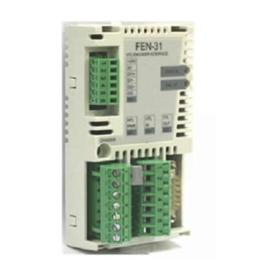
This chapter contains a short description of the FEN-31 HTL Encoder Interface. FEN-31 HTL Encoder Interface FEN-31 is an interface between the control board and an HTL encoder. It supports various types of HTL encoders. A PTC or KTY temperature sensor can be attached to one of the connections of the FEN-31 interface. - Page 12 ACSXXX (optional) ACSXXX FEN-31 Sensor (optional) Encoder FEN-31 connections Overview...
-
Page 13: Compatibility
The shields of connectors X81 and X82 and plug X83 are connected to chassis. The fixing screw connects the chassis to ground. Compatibility FEN-31 is compatible with the following encoders: • Differential push-pull HTL encoders • Single-ended push-pull HTL encoders • Open collector HTL encoders •... - Page 14 Overview...
-
Page 15: Installation
Installation Warning! Follow the safety instructions given in this guide and in the drive’s hardware manual. Setting the supply voltage Warning! Selecting the wrong supply voltage may damage or break the encoder. Two supply voltages are available on pins 4 and 5 in connector X81. -
Page 16: Mounting
Note: Before mounting the module, set the supply voltage jumpers as described above. FEN-31 is inserted into the option slot of the drive. See the drive hardware manual for more information. The module is held in place with plastic retaining clips and one screw. -
Page 17: Terminal Designations
Terminal designations Abbreviations Digital in Digital out Power out HTL supply voltage pin order (X81) Pin Signal name Direction Description +15V_B Supply voltage VCC / external Encoder supply voltage supply +24V_B Supply voltage VCC / external Encoder supply voltage supply 0V_B Common PCT / KTY... - Page 18 HTL input pin order (X82) Name Direction Description A channel A channel - inverted B channel B channel - inverted Marker pulse Marker pulse - inverted Shield TTL encoder emulation output pin order (X83) Name Direction Description EM_A+ Channel A+ EM_B+ Channel B+ EM_Z+...
-
Page 19: Encoder Wiring
Encoder wiring The allocation of cable pairs for each encoder type is described in this section. The encoders should be connected to FEN-31 with a shielded instrumentation cable, preferably with twisted pairs. See also the encoder manual for additional requirements. To prevent the encoder inputs from being disturbed the cable shield must be connected to the chassis. - Page 20 Wiring for differential push-pull HTL encoder Cable pair Signals Connector plug and number name pin number X82-1 X82-2 X82-3 X82-4 X82-5 X82-6 X81-4 COM_B X81-5 FEN-31 Encoder SHLD +15V_B +24V_B PCT/KTY SHLD Wiring diagram for differential push-pull HTL encoder Installation...
- Page 21 Wiring for single-ended push-pull HTL encoder Signals Connector plug and name pin number X82-1 X82-3 X82-5 X81-4 COM_B X81-5 Encoder FEN-31 SHLD +15V_B +24V_B PCT/KTY SHLD Wiring diagram for single-ended push-pull HTL encoder Installation...
- Page 22 X82-1 X82-3 X82-5 X81-4 COM_B X81-5 Encoder FEN-31 SHLD +15V_B +24V_B PCT/KTY SHLD Wiring diagram for single-ended open collector / open emitter HTL encoder To use single-ended open collector and open emitter HTL encoders, the interface unit needs to have pull-up resistors configured.
- Page 23 When transistor opens the circuits the signal line is passively pulled high by the 1.5 kilo-ohm load resistor in FEN-31. Resistor configuration for open emitter HTL encoder For open emitter HTL encoder, the OUT+ channel (A+/B+/Z+) is actively driven high when the transistor closes the circuit.
- Page 24 Configuring the internal pull-up resistor dip switches In FEN-31, a 1.55 kΩ resistor is connected to each signal line (A+, B+, Z+) from one end and the other end is, by default, floating. These floating ends can be connected via DIP switches between connectors X81 and X82.
- Page 25 Note: The DIP switches are OFF by default. Turn them ON only if an encoder that specifically needs a pull-up or pull-down resistor is used. The configuration of the DIP switches is shown in the table below: Encoder type Resistors Notes connected Differential push-pull...
- Page 26 TTL emulation output wiring Cable pair Signals X83 connecting plug number name pin number (9-pin) EM_A+ EM_A- EM_B+ EM_B- EM_Z+ EM_Z- COM_B COM_B FEN-31 EM_A+ EM_A- EM_B+ EM_B- EM_Z+ EM_Z- COM_B COM_B NC - 5 Wiring diagram for TTL emulation output Installation...
- Page 27 Position latch digital input wiring Cable pair Signals X84 connecting header number name pin number (6-pins) +24V_C COM_C DI_1+ DI_1- DI_2+ DI_2- FEN-31 DI1+ DI1- DI2+ DI2- COM_C Wiring diagram for position latch digital input Installation...
-
Page 28: Power Consumption And Cable Length
Power consumption and cable length The power consumption of the module depends on many factors, eg, max. speed of the motor, encoder pulse number per revolution, encoder cable length and leakage capacitance. The following figure shows the approximate power consumption of an encoder with differential outputs, based on actual measurements. -
Page 29: Phasing
Z- or Z or 0 The encoder output channel that leads when the drive runs Forward should be connected to FEN-31 input A, the output channel that trails to FEN-31 input B. The zero reference output channel (usually marked 0, N or Z) needs to be connected in positioning applications only. - Page 30 Installation...
-
Page 31: Fault Tracing
Fault tracing Diagnostic LEDs FEN-31 is equipped with two diagnostic LEDs. The STATUS LED describes the status of the FEN-31 and the ENC ST LED the status of the encoders. Description of the LED signals is presented below. Colour Description... - Page 32 Fault tracing...
-
Page 33: Technical Data
Technical data Dimensions: 31 mm 1.22 in 26 mm 63 mm 1.02 in 2.48 in General • Max. power consumption: 350 mA at 24 V (Max. combined power consumption of encoders, latches and cabling 5W) • Degree of protection: IP20 •... - Page 34 • 6-pin detachable plug, max 1.5 mm wire, tightening torque 0.3 N·m (3 lbf·in) HTL encoder input (X81 & X82) • Supply voltages: - +15 V DC ± 20% 200mA (max.) - HTL encoders - +24 V DC ± 20% 200mA (max.) -HTL encoders - External power supply, if connected, has to be in the range of 10-24 V DC •...
- Page 35 TTL encoder emulation output (X83) • Supports emulation of TTL incremental encoder, 1…65535 pulses / rev, reference mark • CH A, CH B, CH Z: RS-422/485, 500 kHz (max) • Maximum cable length: 100 m • Performance - Speed range: -32768...32767 rpm - Position resolution: 4x pulse count / rev •...
- Page 36 Technical data...
- Page 38 ABB Oy ABB Inc. ABB Beijing Drive Systems AC Drives Automation Technologies Co. Ltd. P.O. Box 184 Drives & Motors No. 1, Block D, FIN-00381 HELSINKI 16250 West Glendale Drive A-10 Jiuxianqiao Beilu FINLAND New Berlin, WI 53151 Chaoyang District Telephone +358 10 22 11 Beijing, P.R.
Need help?
Do you have a question about the FEN-31 and is the answer not in the manual?
Questions and answers