Table of Contents
Advertisement
Quick Links
2UCD190000E001 rev. J
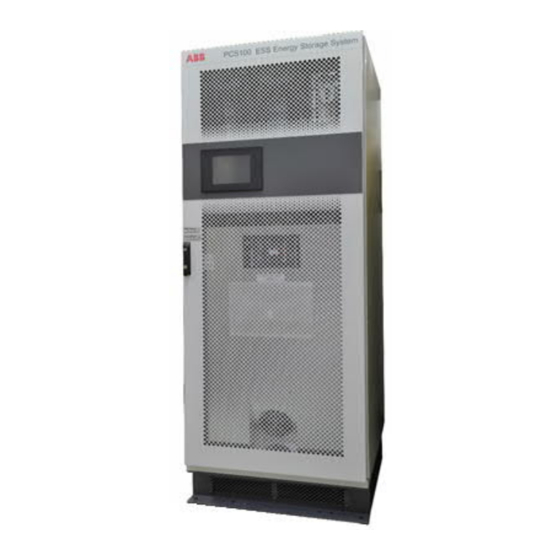
PCS100 ESS
Grid Connect Interface for
Energy Storage Systems
User Manual
Introduction
ABB's PCS100 ESS converter is a grid connect interface
for energy storage systems that allows energy to be
stored or accessed exactly when it is required. Able to
connect to any battery type or energy storage medium,
the PCS100 ESS brings together decades of grid inter-
connection experience and leadership in power conver-
sion to provide seamless system integration and battery
control.
The PCS100 ESS' modular design and advanced control
maximize the availability, value and performance of both
large and small energy storage systems in a variety of
applications. With this optimized use of the energy stor-
age system, the PCS100 ESS helps to deliver exceptional
returns on investment.
The PCS100 ESS allows control of both real power (P)
and reactive power (Q), enabling it to cover a wide range
of system requirements.
Moreover, advanced control features in the Virtual Gener-
ator mode of operation allow this storage system to em-
ulate generator behavior and thus act as a true power
system component.
With these advanced features the PCS100 ESS is the per-
fect solution for applications requiring power system
load levelling, grid stabilization, grid loss detection, grid
compliance for renewable and generation systems and
power quality improvement.
For a comprehensive overview of publications available
for the PCS100 ESS, refer to the inside cover of this pub-
lication. Web links and QR code are also included.
Advertisement
Table of Contents

Subscribe to Our Youtube Channel
Related Manuals for ABB PCS100 ESS


Summary of Contents for ABB PCS100 ESS
- Page 1 For a comprehensive overview of publications available large and small energy storage systems in a variety of for the PCS100 ESS, refer to the inside cover of this pub- applications. With this optimized use of the energy stor- lication. Web links and QR code are also included.
- Page 2 We are an established world force in the design and man- ufacture of power electronics and power protection equip- ment. As a part of ABB, a world leader in electrical technology, we offer customers application expertise, service and support worldwide.
- Page 3 PCS100 ESS – installation and commissioning of the PCS100 ESS Usage This manual should be used during operation and adjustment of the PCS100 ESS. It should be referenced when: – integrating the PCS100 ESS into a complete BESS system –...
- Page 4 CAUTION – Trained Operators All operations on the PCS100 ESS must only be carried out by a trained Operator familiar with the contents of this manual. Hazardous conditions could arise from incorrect adjustment. Ensure power to the product is isolated and locked off before attempting any work on it.
-
Page 5: Table Of Contents
5.1.6 Product Page ........35 5.1.7 Menu Page ........... 36 10 Remote Monitoring ........77 5.1.8 Starting and Stopping the PCS100 ESS . 36 10.1 List of Ports ..........77 5.1.9 Logging in to the GDM ......37 10.2 Cyber Security Information ......77 Module Display Boards ....... - Page 6 Appendix I – Glossary ........153 MODBUS TCP Supported Functions ....130 13 List of Related Documentation ....154 MODBUS RTU RS-485 Supported Functions.. 130 General Status and Measurements Registers . 131 PCS100 ESS User Manual | 2UCD190000E001 rev. J...
-
Page 7: Overview
Providing the grid connect inter- face for all types of energy storage devices, the PCS100 ESS is the perfect solution to connect such energy storage devices to the grid. -
Page 8: Model Definition
One PCS100 ESS cabinet can have up to 6 PCS100 power modules and one PCS100 ESS rack converter up to 32 mod- ules. In case a bigger system is required multiple PCS100 ESS can be connected in parallel. In this case, the units must be tied together with separate transformers or multi-winding transformers. -
Page 9: Mechanical Construction
For racks over 24 modules, two sections of 16-modules are required. Therefore, there is not distinction where it is located. By default, the code for busbar requirement will be C PCS100 ESS User Manual | 2UCD190000E001 rev. J... -
Page 10: Options
2 Model Definition Options This specifies the different options available for the PCS100 ESS either cabinet or rack solution. Any other configuration not specified in this document will be denoted with a +C. +T000 = Tx ready (1 and 2 modules cabinet only) - Page 11 PCS100 19-16C-B22 PCS100 19-24C-B3C PCS100 19-22C-B3D Further information about rack’s components con- nection can be found in the PCS100 ESS Wiring Di- agram, 2UCD190xxxE301. Any other configuration not specified in this docu- ment will be a customized solution (contact factory) PCS100 19-32C-B4C PCS100 ESS User Manual | 2UCD190000E001 rev.
-
Page 12: Pcs100 Ess Model Range
2.3 PCS100 ESS Model Range The model ratings of the PCS100 ESS are defined by the number of power modules used to construct the system. The PCS100 ESS product range is summarized in section 2.3.1 for D-type modules and in section 2.3.2 for C-type modules. -
Page 13: Pcs100 Ess C-Type Model Range
Refer to section 2.1.3 for the right code according the bus bars termination Place C for center termination (2 m rack on the right) or D for center termination (2 m rack on the left) PCS100 ESS User Manual | 2UCD190000E001 rev. J... -
Page 14: Technical Specification
4kV D-type module 6kV C-type module Note: The PCS100 ESS system is rated for use in systems which will not be subject to impulse voltages exceeding their over- voltage rating. Suitably rated surge protection devices (SPDs) should be connected from + and - to earth in applications where surge voltage may exceed the overvoltage rating (e.g.: remote connected DC sources). -
Page 15: Standards And Certifications
Maximum, voltage to ground +/- 600Vdc Note: The PCS100 ESS system is in systems which will not be subject to impulse voltages exceeding their over- voltage rating. Suitably rated surge protection devices (SPDs) should be connected from + and - to earth in applications where surge voltage may exceed the overvoltage rating (e.g.: remote connected DC sources). -
Page 16: Service
It is worth noting that on cabinet versions the Auxiliary Master Module is 230Vac 50/60Hz, but is always sup- plied by an auxiliary “Z” transformer which allows customers to provide power either on 110Vac or 230Vac de- pending on the connection of the primary windings of such auxiliary transformer. PCS100 ESS User Manual | 2UCD190000E001 rev. J... -
Page 17: Sub-Assemblies
1000 mm, giving a maximum of 16 modules (max. 8 modules per rack section). For PCS100 ESS systems requiring more than 16 modules, two racks can be connected with a cen- ter termination as explained in more detail in section Error! Reference source not found.. -
Page 18: Pcs100 Modules
IGBT technology the PCS100 modules have minimum impact on power quality of the supply network (harmonics and power factor). They are delivered in the compact package shown in Figure 4-3. Figure 4-2: Diagram of a PCS100 module Figure 4-3: PCS100 Power Module PCS100 ESS User Manual | 2UCD190000E001 rev. J... -
Page 19: Pcs100 Master Module
Connections on the Master Module The PCS100 ESS includes several control and control power connections for local and remote control and moni- toring of the system. All terminals are located on the PCS100 Master Module and are suitable for wires up to 2.5 cross section. - Page 20 Stop/Inhibit/Reset - return Dry contact only: Stop on open edge: Inhibit while Stop/Inhibit/Reset – input open; Reset on open edge PTC input (e.g. for transformer supervision) PTC input (e.g. for transformer supervision) PCS100 ESS User Manual | 2UCD190000E001 rev. J...
Need help?
Do you have a question about the PCS100 ESS and is the answer not in the manual?
Questions and answers