ABB FEN-01 Quick Manual
Ttl encoder interface
Hide thumbs
Also See for FEN-01:
- User manual (32 pages) ,
- Quick manual (18 pages) ,
- User manual (38 pages)
Advertisement
Available languages
Available languages
Quick Links
Advertisement

Related Manuals for ABB FEN-01


Summary of Contents for ABB FEN-01
- Page 1 Deutsch ..... . 7 Italiano..... . 12 3AFE68784956 Rev D Effective: 28.04.2023 2023 ABB Oy. All rights reserved.
-
Page 2: Safety Instructions
Quick guide - FEN-01 Introduction This manual contains the very basic information about installing the FEN-01 TTL Encoder Interface. For complete documentation see FEN-01 TTL Encoder Interface User’s Manual (3AFE68784603 [English]). Safety instructions WARNING! All electrical installation and maintenance work on the drive must be carried out by qualified electricians. - Page 3 4. Fasten the screw (included) to the stand-off. If you need to remove the adapter module after it has been installed into the drive, use a suitable tool (e.g. small pliers) to carefully pull out the locking tab. Quick guide - FEN-01...
- Page 4 The module does not provide a safe isolation from the drive. The encoders should be connected to the FEN-01 with a shielded instrumentation cable, preferably with twisted pairs. See also the encoder manual for additional requirements.
-
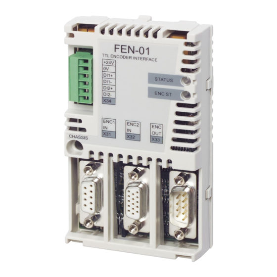
Page 5: Layout And Connections
TTL encoder input with commutation signal support and PTC support (X32) TTL encoder output (X33) 2 digital latch inputs (X34) 63 mm 2.48 in Encoder voltage selection jumper (X301) Locking tab FEN-01 VCC_ENC_1 COM_C VCC_ENC_1 Optional COM_C Quick guide - FEN-01... - Page 6 FEN-01 VCC_ENC_2 COM_B COM_B SENSOR EM_A+ EM_A- FEN-01 EM_B+ EM_B- EM_Z+ EM_Z- COM_B COM_B COM_B Optional COM_B DI1+ DI1- FEN-01 DI2+ DI2- COM_C Quick guide - FEN-01...
- Page 7 Kurzanleitung - FEN-01 Einleitung Diese Anleitung enthält grundlegende Informationen zur Installation des FEN-01 TTL-Inkrementalgeber-Schnittstellenmoduls. Vollständige Dokumentation siehe FEN-01 TTL Encoder Interface User’s Manual (3AFE68784603 [Englisch]). Sicherheitsvorschriften WARNUNG! Alle elektrischen Installations- und Wartungsarbeiten am Frequenzumrichter müssen von qualifiziertem Fachpersonal ausgeführt werden.
-
Page 8: Montage
3. Die Verriegelungsnase hineindrücken (8). 4. Befestigen Sie das Modul mit der Schraube (mitgeliefert). Wenn das Adaptermodul nach dem Einbau in den Frequenzumrichter entfernt werden muss, verwenden Sie ein geeignetes Werkzeug (z. B. eine kleine Zange), um die Verriegelungsnase vorsichtig herauszuziehen. Kurzanleitung - FEN-01... - Page 9 Isolierung vorhanden ist. Das Modul ermöglicht keine sichere Trennung vom Frequenzumrichter. Die Geber müssen mit einem geschirmten Instrumentenkabel, vorzugsweise verdrillten Leiterpaaren, an das FEN-01 angeschlossen werden. Zusätzliche Anforderungen siehe das Geberhandbuch. Das Anzugsmoment beträgt 0,3 Nm (2,7 lbf·in.).
- Page 10 Aufbau und Anschlüsse Diagnose-LEDs Befestigungsschraube TTL-Inkrementalgebereingang (X31) TTL-Inkrementalgebereingang mit Kommutie- rungssignal- und PTC-Unterstützung (X32) TTL-Inkrementalgeberausgang (X33) 2 digitale Referenziersignaleingänge (X34) 63 mm 2,48 in Jumper für Inkrementalgeber-Spannungsauswahl (X301) Verriegelungsnase FEN-01 VCC_ENC_1 COM_C VCC_ENC_1 Optional COM_C Kurzanleitung - FEN-01...
- Page 11 FEN-01 VCC_ENC_2 COM_B COM_B SENSOR EM_A+ EM_A- FEN-01 EM_B+ EM_B- EM_Z+ EM_Z- COM_B COM_B COM_B Optional COM_B DI1+ DI1- FEN-01 DI2+ DI2- COM_C Kurzanleitung - FEN-01...
-
Page 12: Istruzioni Di Sicurezza
Guida rapida - FEN-01 Introduzione Il presente manuale contiene le informazioni base sull'installazione- dell'Interfaccia encoder FEN-01 TTL. Per una completa documentazione, fare riferimento al Manuale utente Interfaccia Encoder FEN-01 TTL (codice: 3AFE68784603). Istruzioni di sicurezza AVVERTENZA! Tutti gli interventi di installazione e manutenzione elettri- casul convertitore di frequenza devono essere eseguiti esclusivamente daelettricisti qualificati. - Page 13 3. Spingere la linguetta di blocco verso l'interno (8). 4. Fissare la vite (inclusa) all’isolatore. Se occorre rimuovere il modulo adattatore dopo che è stato installato nel convertitore, usare un utensile idoneo (ad es. pinze piccole) per estrarre con cautela la linguetta di blocco. Guida rapida - FEN-01...
- Page 14 Il modulo non fornisce un isolamento sicuro dal convertitore di frequenza. Gli encoder dovrebbero essere collegati all'interfaccia FEN-01 con uncavo per strumentazione schermato, preferibilmente con doppiniintrecciati. Per ulteriori informazioni consultare anche il manualedell'encoder.
- Page 15 Ingresso encoder TTL con supporto segnale dicommutazione e supporto PTC (X32) Uscita encoder TTL (X33) 2 ingressi registrazione digitali (X34) 63 mm 2,48 in Ponticello di selezione tensione encoder (X301) Linguetta di blocco FEN-01 VCC_ENC_1 COM_C VCC_ENC_1 opzionale COM_C Guida rapida - FEN-01...
- Page 16 FEN-01 VCC_ENC_2 COM_B COM_B SENSORE EM_A+ EM_A- FEN-01 EM_B+ EM_B- EM_Z+ EM_Z- COM_B COM_B COM_B opzionale COM_B DI1+ DI1- FEN-01 DI2+ DI2- COM_C Guida rapida - FEN-01...
Need help?
Do you have a question about the FEN-01 and is the answer not in the manual?
Questions and answers