Advertisement
Quick Links
Sigtronics SPA-400 TSO Installation and Operating Instructions
INTRODUCTION
ATTENTION INSTALLER: To assure a trouble free installation, please
read the entire instructions through once before beginning.
The Sigtronics' SPA-400 is a voice actuated (VOX) intercom for up to four
headset positions with transmit through the aircraft radio capability
using your push-to-talk switches.
Three controls are provided:
Power Switch — Turns unit on and off.
Volume Control — Controls the intercom volume.
Squelch Control — Allows the setting of voice actuated (VOX)
operation of the intercom for variations in background noise levels
and differences in headset microphones.
SPA-400 SYSTEM SPECIFICATIONS
CONFIGURATION – The SPA-400 Intercom system is specifically
designed for permanent, panel mounted installation in aircraft.
COMPATIBILITY – Sigtronics SPA-400 intercoms have been designed to
operate with all standard general aviation aircraft radios and headsets.
SIZE: Panel – 1" x 2½". Chassis – 1" high x 2½" wide x 4 3 ⁄ ₁₆ " deep.
Can be mounted either horizontally or vertically in the aircraft panel.
WEIGHT: 4.5 ounces (SPA-400 intercom unit with panel and knobs).
Jacks and wiring harness weigh (5.5 ounces maximum).
INPUT POWER: 11 VDC through 32 VDC. Maximum current drain 0.06
amps @ 28 volts
WARRANTY: SPA-400 intercoms are constructed of high quality
components and carry a five year parts and labor warranty.
FAA TSO: C50b ENV. CAT (DO-160) CFBBBX
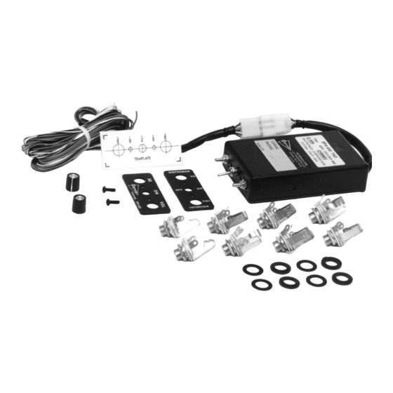
HARDWARE SUPPLIED
Intercom unit, instructions, and the following hardware:
Headphone Output Jacks - Accept standard 0.250" aircraft
headphone plugs. ........................................................................................ 4
Microphone Input Jacks - Accept standard 0.206" aircraft
microphone plugs. (U93 plug compatible jacks can be used in
place of the jacks provided. ..................................................................... 4
Mic Jack Insulating Washers, Flat ........................................................... 4
Mic Jack Insulating Washers, Shoulder ................................................ 4
Intercom Panel - lettered on both sides. ............................................. 1
Intercom Control Knobs ............................................................................ 2
Switch Nut ....................................................................................................... 1
Mounting Screws 4-40 x ½ ....................................................................... 2
Drill Template - Adhesive backed hole size pattern for
drilling aircraft panel. ................................................................................. 1
Aircraft / Intercom Interface Cable (4 feet long) ............................... 1
Figure 1
The Sigtronics' SPA-400 has been designed to mount either horizontally
or vertically in your aircraft panel. All necessary mounting hardware
has been supplied for a 4-way installation. (A round faceplate is also
available from Sigtronics to fit a 2¼" round instrument hole).
The location selected requires a minimum front panel area of 2½" by
1". Depth required behind panel is 4 ³ ⁄ ₁₆ " plus cable access.
Caution: Move aircraft flight controls through limits of travel while
observing selected area to make sure rear of intercom and cable will
not interfere with aircraft control components.
PANEL PREPARATION:
1. Position adhesive template on aircraft panel in selected area.
2. Center punch each hole at cross lines. (The five holes are in straight
3. Drill ¹ ⁄ ₈ " pilot hole all five places.
4. Enlarge holes to ¼" and ³ ⁄ ₈ " per template.
Figure 2
MOUNTING CHASSIS: See Figure 2.
1. Remove switch nut from intercom ON-OFF switch bushing.
2. Remove knobs from Volume and Squelch controls. NOTE: DO NOT
3. Remove two 4-40 panel screws and remove panel from the chassis.
Specialists in "SOUND" Management
178 East Arrow Highway, San Dimas, CA 91773 ( 909 ) 305-9399
WARNING: This product can expose you to chemicals including
Polyvinyl Chloride, which is known to the State of California to
cause cancer, and Lead, which is known to the State of California
to cause birth defects or other reproductive harm. For more
information go to www.P65Warnings.ca.gov.
CHASSIS INSTALLATION
line and equally spaced 0.4" apart.)
K N O B
S W I TCH
4–40 SCREWS
N U T
K N O B
INTERCOM PANEL
AIRCRAFT PANEL
REMOVE nuts from Volume and Squelch control potentiometers.
D O N OT
R E M OV E
T H E S E
N U T S
INTERCOM CHASSIS
MOD. ADJ.
Advertisement

Subscribe to Our Youtube Channel
Related Manuals for Sigtronics SPA-400


Summary of Contents for Sigtronics SPA-400
- Page 1 ATTENTION INSTALLER: To assure a trouble free installation, please read the entire instructions through once before beginning. The Sigtronics’ SPA-400 is a voice actuated (VOX) intercom for up to four headset positions with transmit through the aircraft radio capability using your push-to-talk switches.
- Page 2 Counter-clockwise rotation decreases 909) 305-9399 modulation level. This adjustment sometimes needs to be made after www.sigtronics.com initial installation of the intercom or if a new radio is installed. (The output is set for unity gain at Sigtronics.)
- Page 3 JACK JACK JACK JACK JACK PASSENGER 2 PASSENGER 1 CO-PILOT PILOT SPA-400 Installation Drawing Figure 4 Table 1 Plug Pin # Wire Color Function Connect To: White / Black Pilot Mic Input Ring Terminal of Pilot Intercom Mic Input Jack...
Need help?
Do you have a question about the SPA-400 and is the answer not in the manual?
Questions and answers