Advertisement
Quick Links
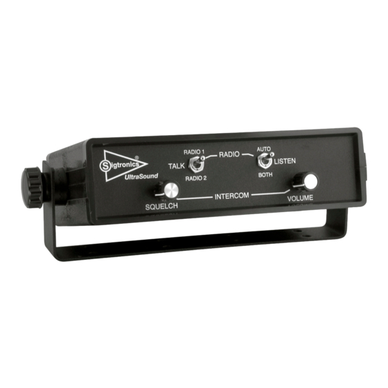
Sigtronics UltraSound Emergency Intercom System
INTRODUCTION
ATTENTION INSTALLER: To assure a trouble free installation,
please read these entire instructions through once before
beginning.
The Sigtronics UltraSound Emergency Intercom System, when used
with Sigtronics noise attenuating headsets provides the emergency
apparatus crew with clear, hands free, voice activated (VOX) intercom.
The system also allows full radio monitoring at all headset positions
as well as radio transmit capability from selected headsets via Push-
To-Talk (PTT) switches.
Applications: The unit is designed for fire apparatus, rescue and
ambulance vehicles, marine emergency equipment, airport ground
vehicles, and mobile emergency command centers.
S
igtronics
US-12D and US-12S
INSTALLATION AND OPERATING INSTRUCTIONS
US-12S
Specialists in "SOUND" Management
®
178 East Arrow Highway, San Dimas, CA 91773 (909) 305-9399
Voice Activated Intercom (VOX) feature allows "hands free" com-
munication between headsets connected to the UltraSound unit.
Start speaking and the intercom turns on instantly to relay your
message clearly to the other headsets. Stop talking and it turns off
to reduce background noise.
Up to Twelve Headset Positions can be connected to the Ultra-
Sound unit models US-12S and US-12D. More headset positions can
be achieved by wiring additional jacks in parallel. Only one headset,
however, can be plugged into paralleled jacks at one time. This
paralleled jack scheme is most commonly used on pumper trucks
at the pump panel. In this case, the Driver plugs his headset into his
jack while driving. He then unplugs and plugs into the pump panel
when he arrives on scene.
US-12D
Advertisement

Related Manuals for Sigtronics US-12S


Summary of Contents for Sigtronics US-12S
- Page 1 (VOX) intercom. The system also allows full radio monitoring at all headset positions Sound unit models US-12S and US-12D. More headset positions can as well as radio transmit capability from selected headsets via Push- be achieved by wiring additional jacks in parallel.
-
Page 2: Control Functions
Installation Overview: at one time on intercom. Four of the twelve have radio transmit capability. The US-12S is designed for use with a single vehicle radio. Sigtronics has simplified the installation process, to assure perfect The US-12D is identical to the US-12S but can accommodate two operation. - Page 3 Headset Jack Placement: It is assumed that it has already been determined which positions Sigtronics provides two ways to mount the headset jacks for the on the vehicle will have headsets. At this stage, it is helpful to have UltraSound unit: a headset handy to physically gauge the best place for a particular jack.
- Page 4 Figure 3. Both jack insulating washers must be used. Refer to the UltraSound Wiring Diagram for the exact wiring infor- mation. Figure 4 for US-12S and Figure 5 for US-12D intercoms. The Jacks have to be insulated from mounting spot to minimize...
-
Page 5: Headset Jack
CREW #4 HEADSET JACK CREW #5 HEADSET JACK – (J4-3) TAN CREW #6 HEADSET JACK – US-12S (SINGLE RADIO) WIRING DIAGRAM (J4-4) TAN CREW #7 HEADSET JACK – NOTES: (J4-5) TAN 1) CONNECT EITHER VIOLET WIRE TO THE RADIO SPEAKER HI OUTPUT. - Page 6 (J4-7) TAN 2) CONNECT EITHER WHITE WIRE TO THE RADIO PUSH-TO-TALK (PTT) KEY LINE INPUT. CONNECT THE REMAINING WHITE WIRE TO THE PTT KEY LINE RETURN (PTT LO). CREW #10 HEADSET JACK – (J4-8) TAN US-12S US-12d i igtronicS ltra oUnd...
- Page 7 4. Check specific “bad” headset jack wiring for: units are designed for negative ground vehicles only. They can be used on positive ground vehicles only if a Sigtronics Positive a) Microphone wire (jack ring terminal) open or shorted to Ground Adapter is used. Contact your Sigtronics dealer on pricing ground.
- Page 8 UltraSound red wire will usually accomplish the increase the vehicle engine rpm from idle to about 1500 RPM and same thing. Do not use the type of filter that installs on or near US-12S US-12d i igtronicS...
- Page 9 Refer to the UltraSound Wiring Diagram - Figure 4 for RADIO 2 US-12S units or Figure 5 for US-12D units. Only the radio functions are shown for the radio end of the UltraSound Radio Interface Cable. RADIO...
- Page 10 If radio reception and transmission through the connections for loose or corroded connections) or. . . UltraSound unit are fine, for US-12S units this completes the installa- ii) Excessive noise is generated directly by the vehicle’s electrical tion. Skip to the “System Operation” section. If everything is OK for / charging system - most commonly known as alternator US-12D units, skip to the “Radio 2 Hook Up”...
- Page 11 3. With the radio’s hand mic, transmit as normal, to the remote station. Transmit long enough so that the receiving station can This completes the UltraSound installation. get “calibrated” to your transmission (voice) level. US-12S US-12d i SigtronicS igtronicS ltra...
-
Page 12: System Operation
“AUTO” position allows you to hear the radio that the RADIO 1/RADIO 2 switch is set to. with siren on). b) “BOTH” position permits you to hear both the radios at the same time. US-12S US-12d i igtronicS ltra oUnd... - Page 13 1.667 1.667 0.2 DIA + 0.01 0.25 0.50 MOUNTING BRACKET BOTTOM VIEW Sigtronics UltraSound Intercom Typical Installation Dimensions 7-18-2011 UltraSound_Installation_Dimensions.pdf Sigtronics Installation Hot Line Number: 1-800-367-0977 ext. 8 igtronics Monday through Friday, 8:00 a.m. to 4:30 p.m. Pacific Time ®...
Need help?
Do you have a question about the US-12S and is the answer not in the manual?
Questions and answers