
Subscribe to Our Youtube Channel
Related Manuals for Hubner Cobolt 05-01 Series


Summary of Contents for Hubner Cobolt 05-01 Series
- Page 1 OWNERS MANUAL | Cobolt 05-01 Series | D0106-N MARCH 2023 Cobolt 05-01 Series High Power | Single Frequency | CW Diode pumped lasers 320 nm 491 nm 640 nm 355 nm 515 nm 660 nm 457 nm 532 nm 1064 nm...
- Page 2 OWNERS MANUAL | Cobolt 05-01 Series | D0106-N MARCH 2023 2 | 40...
-
Page 3: Table Of Contents
OWNERS MANUAL | Cobolt 05-01 Series | D0106-N MARCH 2023 CONTENTS Introduction Safety General Beam Hazards Safety features Equipment Safety Warning and Identification Labels Overview – Cobolt 05-01 Model number Configuration Laser Head Laser Controller Controller Cable Power Supply Requirements Thermal Management Overview –... - Page 4 OWNERS MANUAL | Cobolt 05-01 Series | D0106-N MARCH 2023 Troubleshooting Warranty and Maintenance Service Disclaimers Compliance (CDRH models only) 4 | 40...
-
Page 5: Introduction
The Cobolt 05-iE is a fully integrated laser device, including all control electronics. The Cobolt 05-iE completely eliminates the need for an external controller, combining the trusted laser performance of Cobolt 05-01 Series in a compact, self-contained device. -
Page 6: Safety
OWNERS MANUAL | Cobolt 05-01 Series | D0106-N MARCH 2023 Safety General Cobolt 05-01 lasers are Class IIIB (3B) and Class IV (4) laser products that emit laser radiation within the visible and Near Infrared (NIR) spectrum. Residual emissions from the pump diode are contained within the laser head housing via filtering optics. -
Page 7: Beam Hazards
OWNERS MANUAL | Cobolt 05-01 Series | D0106-N MARCH 2023 Symbols in the manual WARNING – LASER RADIATION This symbol is used to call attention to important laser safety information WARNING – STATIC MAGNETIC FIELD This symbol is used to call attention to important magnetic field safety information CAUTION –... - Page 8 OWNERS MANUAL | Cobolt 05-01 Series | D0106-N MARCH 2023 CAUTION Use of controls or adjustments or performance of any procedures other than those specified herein may result in exposure to hazardous radiation. The table below describes the irradiance in W/cm and appropriate level of eye protection in terms of optical density (OD) for each product line.
-
Page 9: Safety Features
OWNERS MANUAL | Cobolt 05-01 Series | D0106-N MARCH 2023 Safety features The laser is equipped with all required safety features as described in the laser safety standard 60825-1. Disabling any safety features negate the CE/CDRH compliance of this product. If any part of the delivered equipment is replaced with a part not supplied by Cobolt or if the equipment is not properly grounded system may not conform to CE / CDRH compliance standards listed in section 14 : Compliance (CDRH models only). -
Page 10: Warning And Identification Labels
OWNERS MANUAL | Cobolt 05-01 Series | D0106-N MARCH 2023 Warning and Identification Labels The upper face of the laser head contains a yellow label with laser safety warning and classification information, the wavelength and maximum power of the unit. It also shows the location of the laser beam from the aperture and indicates the open and close positions of the manual shutter. -
Page 11: Overview - Cobolt
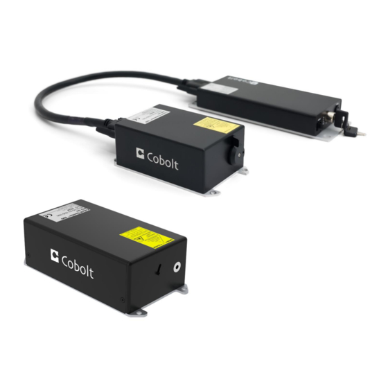
OWNERS MANUAL | Cobolt 05-01 Series | D0106-N MARCH 2023 Overview – Cobolt 05-01 Cobolt 05-01 laser systems consist of four main parts: the laser head, the Controller, the Cable and the Power Supply (not shown). The cable provided should always be used to connect the laser head with the Controller. Always install the laser system to a properly grounded power outlet. -
Page 12: Laser Head
OWNERS MANUAL | Cobolt 05-01 Series | D0106-N MARCH 2023 The standard CDRH model consists of: • Laser head • Controller with key switch • Keys • 1 m Controller Cable • 15 V / 6 A DC power supply unit The OEM system is supplied without a key switch on the controller. -
Page 13: Controller Cable
OWNERS MANUAL | Cobolt 05-01 Series | D0106-N MARCH 2023 5.6. The operation of the laser can be controlled and monitored via the data port that supports either USB or RS-232 commands. See Section 8.3 for further details. RS-232 controllers may also be delivered with a RS-232 to USB adaptor. -
Page 14: Overview - Cobolt 05-Ie
OWNERS MANUAL | Cobolt 05-01 Series | D0106-N MARCH 2023 Overview – Cobolt 05-iE Cobolt 05-iE laser systems consist of three main parts: the laser head, the key control box, and the Power Supply (not shown). The cable provided should always be used to connect the laser head with the Controller. Always install the laser system to a properly grounded power outlet. -
Page 15: Configuration
OWNERS MANUAL | Cobolt 05-01 Series | D0106-N MARCH 2023 Configuration CDRH Compliant The CDRH compliant system is supplied with a key switch on the key control box, which must be connected, along with a remote interlock connector. Once power is supplied, laser radiation starts when the key is turned from the OFF position to the ON position. -
Page 16: Power Supply Requirements
OWNERS MANUAL | Cobolt 05-01 Series | D0106-N MARCH 2023 Power Supply Requirements An appropriate Power Supply Unit (PSU) is supplied by Cobolt with the laser and must be plugged into a properly grounded standard power outlet. The output from this PSU is 12 VDC / 6.67 A. The power supply accepts 100 – 240 V AC and 50-60 Hz. -
Page 17: System Description
OWNERS MANUAL | Cobolt 05-01 Series | D0106-N MARCH 2023 System Description The information presented here is believed to be accurate and is subject to change without notice. The specifications contained herein can only be guaranteed at 100% of nominal power after warm-up is complete, within the operation environment constraints listed below. - Page 18 OWNERS MANUAL | Cobolt 05-01 Series | D0106-N MARCH 2023 Operation and Environmental Specifications 05-01 Zydeco /Bolero 05-iE* Power supply 15 VDC, 6 A 12 V, 6.67 A Power consumption, total system < 65 W (typical < 30 W) º...
- Page 19 OWNERS MANUAL | Cobolt 05-01 Series | D0106-N MARCH 2023 Mechanical Interfaces 05-01 05-iE Laser Head 125 x 70 x 45 mm 134 x 70 x 45 mm (4.9 x 2.8 x 1.8 inches) (5.3 x 2.8 x 1.8 inches)
-
Page 20: Mechanical Drawings
OWNERS MANUAL | Cobolt 05-01 Series | D0106-N MARCH 2023 Mechanical Drawings Laser Head 05-01 Laser head mechanical outline. Dimensions in mm [inches]. Laser Controller Gen 5b – 05-01 Controller mechanical outline. Dimensions in mm [inches]. 20 | 40... - Page 21 OWNERS MANUAL | Cobolt 05-01 Series | D0106-N MARCH 2023 Laser Head 05-iE Laser head mechanical outline. Dimensions in mm [inches]. Key control box - 05-iE 21 | 40...
-
Page 22: Remote Interlock Connector
OWNERS MANUAL | Cobolt 05-01 Series | D0106-N MARCH 2023 Remote Interlock Connector The remote interlock connector is located at pin 1 and 2 of the Molex connector on the control I/O connector. The connector can be short-circuited with an interlock jumper (included at delivery) for operation of the laser. To use the remote interlock connector with an external switch, connect a pin 1 and 2 on a Molex plug. -
Page 23: Pin Assignment - 05-01 Controller
OWNERS MANUAL | Cobolt 05-01 Series | D0106-N MARCH 2023 Pin assignment – 05-01 Controller All equipment connected to the system should be limited energy as described by IEC 61010:1. Controller I/O connector Manufacturer Molex 90130-3206, mates with 90143-0006. Function... -
Page 24: Pin Assignment - 05-Ie
OWNERS MANUAL | Cobolt 05-01 Series | D0106-N MARCH 2023 Pin assignment – 05-iE All equipment connected to the system should be limited energy as described by IEC 61010:1. Laser head I/O - CTRL The pin configuration for the 14 pin Molex connector on the laser head is described in the table below. -
Page 25: Pin Assignment - 05-Ie - Key Control Box
OWNERS MANUAL | Cobolt 05-01 Series | D0106-N MARCH 2023 Power connector The pin configuration for the Molex 4-pin connector is described below. Function – Ground – Ground + 12 V - DC 4 pin Molex socket on laser head + 12 V - DC Pin assignment –... - Page 26 OWNERS MANUAL | Cobolt 05-01 Series | D0106-N MARCH 2023 Data connector – RS 232 The pin configuration for the 9 pin Sub-D (serial) connector on the key control is described in the table below. Function RS-232 TX RS-232 RX 9 pin Sub-D connector for RS-232 communication –...
-
Page 27: Operating Instructions
Operating Modes There are two operating modes: constant power and constant current. The default mode for Cobolt 05-01 series lasers when shipped is constant power. In constant power mode the power is monitored on an internal photodiode, and this is used to regulate the current to maintain a constant power level. -
Page 28: Operation Via Data Port
OWNERS MANUAL | Cobolt 05-01 Series | D0106-N MARCH 2023 Operation via data port Cobolt 05-01 lasers To communicate with a Cobolt 05-01 lasers use the mini-USB data port on the external controller. The appropriate communication cable is provided with all lasers. Determine which communication protocol (USB or RS-232) your system is configured for by either checking the label on the mini-USB data port or from the model number (see 3.1). -
Page 29: Communication Commands
OWNERS MANUAL | Cobolt 05-01 Series | D0106-N MARCH 2023 Communication commands The laser is delivered set in Auto-start mode (see section 6.1 for Auto-start sequence description). As long as DC power is supplied to the system the temperature control elements are always operating to reach set-point values and the laser will be idle waiting for the next command. -
Page 30: Installation Of The Usb Driver
OWNERS MANUAL | Cobolt 05-01 Series | D0106-N MARCH 2023 Installation of the USB driver When connecting a Cobolt laser with to a computer using Windows 8 or earlier (e.g Windows 7, Vista, XP) it is necessary to install the Cobolt signed USB driver. The USB driver can be downloaded from the Cobolt website (hubner- photonics.com). - Page 31 OWNERS MANUAL | Cobolt 05-01 Series | D0106-N MARCH 2023 Click browse, and find folder on your computer where the USB driver is stored. 6. Windows security may warn you that the publisher of the driver is unverified. Choose Install this driver software anyway.
-
Page 32: Cobolt Monitor™ Software
OWNERS MANUAL | Cobolt 05-01 Series | D0106-N MARCH 2023 Cobolt Monitor™ Software The Cobolt Monitor™ software provides a graphical way to monitor the laser performance and to change power, operation mode and other settings. The software can connect to the laser either via RS-232 port or via USB, depending on the system configuration. - Page 33 OWNERS MANUAL | Cobolt 05-01 Series | D0106-N MARCH 2023 Once the laser is connected it can be controlled from the box dedicated for the laser. The interface, found in the following figure, is intended for typical user cases. Only the relevant information is presented on this level, displaying only the status the laser is in and relevant choices to make.
- Page 34 OWNERS MANUAL | Cobolt 05-01 Series | D0106-N MARCH 2023 Mode – Gives a choice of operational modes possible to choose for the laser model. Cobolt Tor™ Series Constant Power, Constant Current, Burst Mode and Constant Repetition Rate (OEM only) operation can be chosen.
- Page 35 OWNERS MANUAL | Cobolt 05-01 Series | D0106-N MARCH 2023 TEC Settings – shows the running status and the fault status for the laser’s internal thermoelectric coolers (TEC). Autostart Program - displays whether the laser is in CDRH or OEM mode and displays the current laser operational status.
- Page 36 OWNERS MANUAL | Cobolt 05-01 Series | D0106-N MARCH 2023 Troubleshooting In the unlikely case of a problem occurring, use the table below to help identify the error. LEDs Status Explanation Action Mains power off Check connections Flashing Temperatures not stabilized...
- Page 37 OWNERS MANUAL | Cobolt 05-01 Series | D0106-N MARCH 2023 Service Due to accuracy tolerances, calibration differences and allowed power drift there may be discrepancies between the Cobolt measurement of the optical output power and the customer measurement equipment. If the output power deviates from the reported value please contact your local sales representative for an online re-calibration.
- Page 38 OWNERS MANUAL | Cobolt 05-01 Series | D0106-N MARCH 2023 Compliance (CDRH models only) The CDRH model lasers (-1100, and -5/700) are designed and manufactured to comply with the EC Low Voltage Directive and the EC EMC Directive in the CDRH-compliant configuration. Cobolt 05-01 laser system consist of a laser head, 1 m controller cable, controller, key and Cobolt-supplied power supply.
- Page 39 OWNERS MANUAL | Cobolt 05-01 Series | D0106-N MARCH 2023 39 | 40...
- Page 40 (Sales in Germany, Switzerland and Austria) Kassel, Germany Phone: +49 561 994 060-0 Fax: +49 561 994 060-13 E-mail: info.de@hubner-photonics.com HÜBNER Photonics Inc. (Sales in USA, Canada, and Mexico) San Jose, California, USA Phone: +1 (408) 708 4351 Fax: +1 (408) 490 2774 E-mail: info.usa@hubner-photonics.com...
Need help?
Do you have a question about the Cobolt 05-01 Series and is the answer not in the manual?
Questions and answers