Advertisement
Quick Links
English
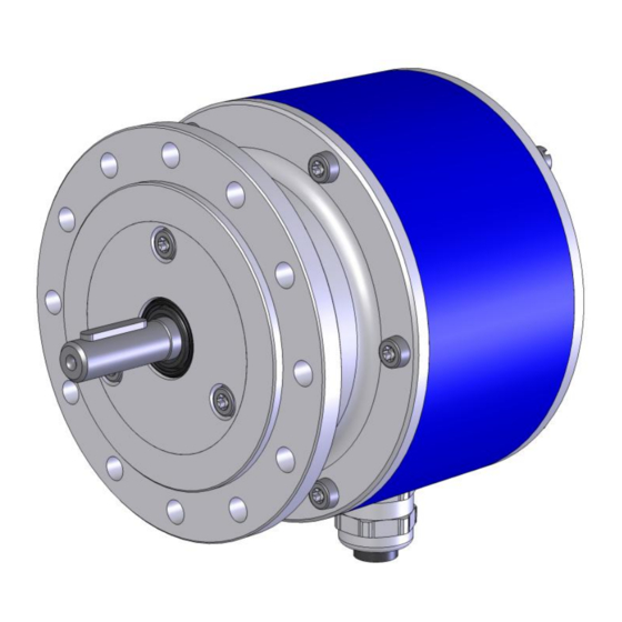
Operating and Assembly Instructions
Incremental Encoder FG 2
Read the Operating and Assembly Instructions prior to
assembly, starting installation and handling!
Keep for future reference!
Translation of the original operating and assembly instructions FG2_MANUAL-en_R8(2016-08-11)ID70199.doc
ID 70199
Advertisement

Subscribe to Our Youtube Channel
Related Manuals for Hubner FG 2 Series


Summary of Contents for Hubner FG 2 Series
- Page 1 English Operating and Assembly Instructions Incremental Encoder FG 2 Read the Operating and Assembly Instructions prior to assembly, starting installation and handling! Keep for future reference! Translation of the original operating and assembly instructions FG2_MANUAL-en_R8(2016-08-11)ID70199.doc ID 70199...
- Page 2 It is strictly forbidden to reproduce this publication or parts of this publication in any form or by any means without the prior written permission of Johannes Hubner Fabrik elektrischer Maschinen GmbH. Subject to errors and changes due to technical improvements.
- Page 3 Incremental Encoder FG 2 Directory 1 General ..........................5 1.1 Information about the Operating and Assembly Instructions ........5 1.2 Scope of delivery ....................... 5 1.3 Explanation of symbols ....................5 1.4 Disclaimer ........................6 1.5 Copyright ........................6 1.6 Guarantee terms ......................6 1.7 Customer service .......................
- Page 4 Incremental Encoder FG 2 6.7 Electrical connection and start up ................18 6.7.1 Preparing cables ....................18 6.7.2 Electrical connection .....................18 7 Dismantling ........................19 7.1 Safety instructions .....................19 7.2 Dismantling the encoder ...................19 8 Faults ..........................20 8.1 Faults table .......................20 9 Inspections ........................21 9.1 Safety instructions .....................21 9.2 Maintenance information ...................21 9.3 Inspection schedule ....................21...
- Page 5 Incremental Encoder FG 2 1 General 1.1 Information about the Operating and Assembly Instructions These Operating and Assembly Instructions provide important instructions for working with the device. They must be carefully read prior to starting all tasks, and the instructions contained herein must be followed.
- Page 6 Incremental Encoder FG 2 1.4 Disclaimer All information and instructions in these Operating and Assembly Instructions have been provided under due consideration of applicable guidelines, as well as our many years of experience. The manufacturer assumes no liability for damages due to: ...
- Page 7 Incremental Encoder FG 2 2.3 Intended use The device has been designed and constructed exclusively for the intended use described here. Series FG 2 Incremental Encoders are used for measurement of rotations, for instance of electrical and mechanical drives and shafts. Claims of any type due to damage arising from non-intended use are excluded;...
- Page 8 Incremental Encoder FG 2 2.6 Special dangers Residual risks that have been determined based on a risk assessment are cited below. 2.6.1 Electrical current DANGER! Life-threatening danger due to electrical shock! There is an imminent life-threatening hazard if live parts are touched. Damage to insulation or to specific components can pose a life-threatening hazard.
- Page 9 Incremental Encoder FG 2 3 Technical Data 3.1 Type plate Below are some nameplates for different device models shown. Without option S or LWL With option S The type plate is located on the outside of the housing and contains the following information: Englisch Deutsch Manufacturer, address...
- Page 10 Incremental Encoder FG 2 3.2 Electrical and mechanical data Pulse Rates 1024, 2048 Connection data 12 V…30 VDC Ripple max. 10 % Supply voltage For UL and CSA Class 2 supplied No load-current approx. 50 mA at 24 V screw-type terminal Type Phoenix ZFKDS 1,5-W-5,08 Connection (0,25 mm²...
- Page 11 Incremental Encoder FG 2 4 Overview additional options 4.1 Option S (overspeed switch) The incremental encoder FG 2 with option S has an insulated switching output. The switching function is realized with a semiconductor, the switching speed is set in our factory (switching hysteresis 10%).
- Page 12 Incremental Encoder FG 2 4.4 Type code AK - 1024 G - 90G - NG Incremental encoder Series Connections Terminal box AKK: Double pulse output Terminal box with connector for ST-compatible fiber optic plug Pulses per rotation 1024, 2048 Basic channel 0° (A) Pulse channel 90°...
- Page 13 Incremental Encoder FG 2 5 Transport, packaging and storage 5.1 Safety instructions for transport CAUTION! Material damage caused by improper transport! Observe the symbols and information on the packaging: Do not throw - risk of breakage Keep dry ...
- Page 14 Incremental Encoder FG 2 6 Installation and commissioning 6.1 Safety instructions Personnel Installation and commissioning must be carried out by skilled technical staff only. WARNING! Observe the safety instructions contained in Chapter 2 when dismantling the device! 6.2 Technical information NOTES! Do not use a hammer or similar tool when installing the device due to the risk of damage occurring to the bearings or coupling!
- Page 15 Incremental Encoder FG 2 6.4 Mounting preparations 1. Ensure all accessories are available (please refer to Chapter 13 Dimension drawings). NOTES! Fastening screws and earth cable are not included in the range of supply. 2. Preparing the place of attachment: Clean the (motor) shaft, centering, bolting surfaces and fastening threads;...
- Page 16 Incremental Encoder FG 2 Lightly grease the (Motor) Schaft (1) an Centerin (9). Fit coupling (2) onto (motor) shaft. NOTES! You must be able to mount the coupling without force. Ream out the bores of used couplings, if necessary! Secure the coupling hub on the (motor) shaft with a grub screw or cheese head screw (10) (depending on the coupling type).
- Page 17 Incremental Encoder FG 2 6.6 Mounting tolerances NOTES! Angle misalignment and parallel displacement between the (motor) shaft and the encoder shaft are mounting errors and should be kept as small as possible. Mounting errors - Cause radial forces to act on the encoder shaft. - Reduce the service life of the bearings and the coupling.
- Page 18 Incremental Encoder FG 2 6.7 Electrical connection and start up NOTES! You must observe applicable EMC guidelines when routing cables! NOTES for UL and CSA! Do only use copper cables! 6.7.1 Preparing cables 1. Strip cable insulation. The cable for the signal and supply line is shielded, the cable for the option S and the cable for LWL will not be shielded.
- Page 19 Incremental Encoder FG 2 6. Connect the supply voltage, the signal cable and possibly option S (please refer to the connection diagrams, Chapter 14). CAUTION! Do not apply supply voltage to the signal outputs, as this will destroy the device! 7.
- Page 20 Check pin assignment; observe connection diagram Signal end stage overloaded Signal interruptions Do not assign unused outputs Do not connect outputs with Outputs short-circuited supply voltage or GND Contact Hubner-Service (page 2) if none of the remedies listed above provides a solution! FG2_MANUAL-en_R8(2016-08-11)ID70199.doc...
- Page 21 Incremental Encoder FG 2 9 Inspections 9.1 Safety instructions WARNING! Skilled technical staff only are permitted to inspect the device and its installation. Observe the safety instructions contained in Chapter 2 when inspecting or working on the device! 9.2 Maintenance information The device is maintenance-free.
- Page 22 Incremental Encoder FG 2 11 Replacement parts The replacement parts listed below can be obtained via the service address on page 2. Replacement parts Comment M 20 x 1.5, cable Ø 9…13 mm EMC cable gland Terminal box cover Including O-Ring and screws Feather key 4 x 4 x 22;...
- Page 23 Incremental Encoder FG 2 12 EC-Declaration of Incorporation FG2_MANUAL-en_R8(2016-08-11)ID70199.doc...
- Page 24 Incremental Encoder FG 2 FG2_MANUAL-en_R8(2016-08-11)ID70199.doc...
- Page 25 Incremental Encoder FG 2 FG2_MANUAL-en_R8(2016-08-11)ID70199.doc...
- Page 26 Incremental Encoder FG 2 13 Dimension drawings FG 2 Construction type B5 HM 11 M 103550 FG2_MANUAL-en_R8(2016-08-11)ID70199.doc...
- Page 27 Incremental Encoder FG 2 FG 2 AKK Construction type B5 HM 15 M 108610 FG2_MANUAL-en_R8(2016-08-11)ID70199.doc...
- Page 28 Incremental Encoder FG 2 FG 2 With 90° angle HM 12 M 104415 FG2_MANUAL-en_R8(2016-08-11)ID70199.doc...
- Page 29 Incremental Encoder FG 2 FG2 with annex Construction type B5 HM 11 M 104353 FG2_MANUAL-en_R8(2016-08-11)ID70199.doc...
- Page 30 Incremental Encoder FG 2 FG 2 with option S Construction type B5 HM 12 M 104789 FG2_MANUAL-en_R8(2016-08-11)ID70199.doc...
- Page 31 Incremental Encoder FG 2 FG 2 with fiber optic option Construction type B5 HM 14 M 108095a FG2_MANUAL-en_R8(2016-08-11)ID70199.doc...
- Page 32 Incremental Encoder FG 2 14 Connection diagrams 14.1 Terminal box NOTES! The connection diagrams are displayed in each terminal box cover! Connection technology AK Connection technology AL Connection technology AKK FG2_MANUAL-en_R8(2016-08-11)ID70199.doc...
- Page 33 Incremental Encoder FG 2 14.2 Connection cable NOTES! The connection diagrams are attached to each cable! Connection cable Connection cable (option S) FG2_MANUAL-en_R8(2016-08-11)ID70199.doc...
Need help?
Do you have a question about the FG 2 Series and is the answer not in the manual?
Questions and answers