Table of Contents
Advertisement
Advertisement
Table of Contents

Subscribe to Our Youtube Channel
Related Manuals for Hubner Cobolt 06-01 Series


Summary of Contents for Hubner Cobolt 06-01 Series
- Page 1 OWNERS MANUAL | Cobolt 06-01 Series | D0136-M AUGUST 2020 Cobolt 06-01 Series Plug and play | Modulatable | CW lasers 375 nm 473 nm 561 nm 730 nm 975 nm 405 nm 488 nm 633 nm 760 nm 415 nm...
- Page 2 OWNERS MANUAL | Cobolt 08-01 Series | D0141-K SEPTEMBER 2020 2 | 60...
-
Page 3: Table Of Contents
OWNERS MANUAL | Cobolt 08-01 Series | D0141-K SEPTEMBER 2020 CONTENTS Introduction Safety General Symbols in the manual Safety features Equipment Safety Quick Start Guide 06-MLD 06-DPL 06-MLD Modulation 06-DPL Modulation Closedown operation Overview Model number Configuration Warning and Identification Labels Laser head Key control box Thermal management... - Page 4 OWNERS MANUAL | Cobolt 08-01 Series | D0141-K SEPTEMBER 2020 Communication commands Cobolt Monitor™ Software Installation Software instructions Troubleshooting Warranty and Maintenance Service Compliance (CDRH models only) Disclaimer 4 | 60...
-
Page 5: Introduction
OWNERS MANUAL | Cobolt 08-01 Series | D0141-K SEPTEMBER 2020 Introduction The Cobolt 06-01 Series offers a compact form factor and a wide wavelength span in a plug and play format. The Cobolt 06-01 Series lasers consist of high-performance fixed wavelength laser modules; modulated laser diodes (MLD) and diode pumped lasers (DPL) cover a spectral range between 375 nm and 975 nm. -
Page 6: Safety
Safety General All Cobolt 06-01 Series lasers are Class IIIB (CDRH), Class 3B (IEC) laser products which emit less than 500 mW of laser radiation within the visible spectrum. The residual emission does not exceed Laser Class 1. Eye and skin exposure to direct or reflected laser light is hazardous and may be extremely harmful. Always wear eye protection appropriate to the beam wavelength and intensity. - Page 7 OWNERS MANUAL | Cobolt 08-01 Series | D0141-K SEPTEMBER 2020 Accessible Emission The table below describes the irradiance in W/cm and appropriate level of eye protection in terms of optical density (OD) for each product line. Product Nominal Output Power Irradiance Eye protection (mW)
-
Page 8: Safety Features
OWNERS MANUAL | Cobolt 08-01 Series | D0141-K SEPTEMBER 2020 Fiber Pigtailed Option All safety recommendations in section 2.1 are also valid for the Cobolt 06-01 series fiber pigtailed laser heads. Additionally, heat generated from absorption of laser radiation by particles on the fiber end may increase the probability of ignition hazards in certain environments. -
Page 9: Equipment Safety
OWNERS MANUAL | Cobolt 08-01 Series | D0141-K SEPTEMBER 2020 Equipment Safety Back Reflection Sensitivity Laser light reflected directly back into the laser head causes damage to the laser diode and results in a dramatic decrease in product lifetime. 06-MLD lasers with a wavelength greater than 600 nm are particularly sensitive, exercise extreme caution. -
Page 10: Quick Start Guide
OWNERS MANUAL | Cobolt 08-01 Series | D0141-K SEPTEMBER 2020 Quick Start Guide 06-MLD Mount the laser on a heat sink or suitable flat surface that provides adequate heat dissipation and connection to ground. Use the four holes on the laser’s base plate to secure it. 2. -
Page 11: 06-Dpl
OWNERS MANUAL | Cobolt 08-01 Series | D0141-K SEPTEMBER 2020 The laser will now start up in continuous-wave, constant current mode at its nominal maximum power level. The power and wavelength may continue to drift for up to 3 minutes while the temperature of the platform stabilizes. - Page 12 OWNERS MANUAL | Cobolt 08-01 Series | D0141-K SEPTEMBER 2020 The laser now goes through the following auto-start sequence: • Temperature stabilization (1-2 min). • Turn the key switch to start the laser. Status LEDs: ON goes on. (CDRH model only) •...
-
Page 13: 06-Mld Modulation
OWNERS MANUAL | Cobolt 08-01 Series | D0141-K SEPTEMBER 2020 06-MLD Modulation There are three ways of modulating the 06-MLD (digital, analog, and on/off modulation), the simplest of which is the on/off modulation feature, which requires no data connection to the laser. For a detailed guide to operating the laser in modulation modes see section 6 : Modulation mode operation. -
Page 14: 06-Dpl Modulation
OWNERS MANUAL | Cobolt 08-01 Series | D0141-K SEPTEMBER 2020 06-DPL Modulation The 06-DPL can be modulated with digital modulation, analog modulation or a combination of the two. The simplest of which is the digital modulation. For a detailed guide to operating the laser in modulation modes see section 6 : Modulation mode operation. -
Page 15: Overview
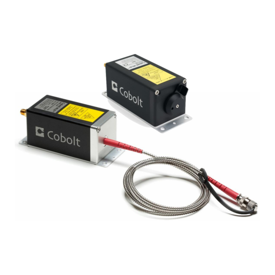
Overview Cobolt 06-01 Series laser systems consist of four main parts: the laser head, key control box, cable between laser head and key control box, and the power supply (not shown). Always install the laser system to a properly grounded power outlet. -
Page 16: Configuration
OWNERS MANUAL | Cobolt 08-01 Series | D0141-K SEPTEMBER 2020 Configuration CE/CDRH Compliant The CE/CDRH compliant system is supplied with a key control box, which must be connected, along with a remote interlock connector. Once power is supplied, laser emission starts when the key is turned from the OFF position to the ON position. -
Page 17: Warning And Identification Labels
OWNERS MANUAL | Cobolt 08-01 Series | D0141-K SEPTEMBER 2020 Warning and Identification Labels The upper face of the laser head contains a yellow label with laser safety warning and classification information, the wavelength and maximum power of the unit. It also shows the location of the laser beam aperture and indicates the open and closed positions of the manual shutter. - Page 18 OWNERS MANUAL | Cobolt 08-01 Series | D0141-K SEPTEMBER 2020 Fiber pigtailed laser head Manufacturer Identification Labels OEM Label Aperture Warning Labels CE / CDRH compliant label Laser Notice No. 50 Label CDRH models shipped to USA 18 | 60...
-
Page 19: Laser Head
OWNERS MANUAL | Cobolt 08-01 Series | D0141-K SEPTEMBER 2020 Laser head The laser head contains the laser cavity, beam shaping optics, thermoelectric coolers (TEC) for temperature control and, in 06-DPLs, an optical feed-back loop which ensures long-term power stability of the emitted laser beam. The laser head also features a manual mechanical shutter, a laser hazard label and a laser classification label. -
Page 20: Power Supply Requirements
For assistance in thermal management and system integration, please contact your sales representative, see section 12. Heat Sink Requirements for Cobolt 06-01 Series. Power supply requirements An appropriate Power Supply Unit (PSU) is supplied by Cobolt with the laser and can be plugged into a standard power outlet. -
Page 21: System Description
OWNERS MANUAL | Cobolt 08-01 Series | D0141-K SEPTEMBER 2020 System Description The information presented here is believed to be accurate and is subject to change without notice. The specifications contained herein cannot be guaranteed outside of normal operational conditions. Optical specifications - free beam lasers Center wavelength (nm) -
Page 22: Modulation Specifications
OWNERS MANUAL | Cobolt 08-01 Series | D0141-K SEPTEMBER 2020 Center Wavelength (nm) Power (mW) Power stability over 8 hrs < 2 % Exit ferrule End cap No End cap Fiber Output FC/APC, 8°, non-collimated Fiber Type SM/PM Polarization PER > 100:1, vertical ± 2° Standard fiber length 1 (m) / ... -
Page 23: Operation And Environmental Specifications
OWNERS MANUAL | Cobolt 08-01 Series | D0141-K SEPTEMBER 2020 Operation and Environmental Specifications Power supply requirements 5 VDC, 3 A 5 VDC, 5 A Intended use environment Laboratory (indoor) 50 C Maximum baseplate temperature º Ambient temperature, operation 10 - 40 º... - Page 24 OWNERS MANUAL | Cobolt 08-01 Series | D0141-K SEPTEMBER 2020 Laser Head 06-MLD mechanical outline. Dimensions in mm [inches]. 06-DPL mechanical outline. Dimensions in mm [inches]. 24 | 60...
- Page 25 OWNERS MANUAL | Cobolt 08-01 Series | D0141-K SEPTEMBER 2020 Fiber Pigtailed Laser head mechanical outline. Dimensions in mm [inches]. Key control box 06-MLD 06-DPL 06-01 Series Key control box, mechanical outline. Dimensions in mm [inches]. 25 | 60...
-
Page 26: Remote Interlock Connector
OWNERS MANUAL | Cobolt 08-01 Series | D0141-K SEPTEMBER 2020 Remote Interlock Connector The laser is equipped with a remote interlock connector that prevents current flow through the diode when the circuit is open. After the remote interlock connector has been opened the laser will need to be reset by disconnecting from and then reconnecting to the power supply in order to start again or toggling the key switch. -
Page 27: Direct On/Off Control
OWNERS MANUAL | Cobolt 08-01 Series | D0141-K SEPTEMBER 2020 Direct On/Off control 06-MLD This feature is not available for 06-MLD. 06-DPL The Direct On/Off control feature enables turning the laser On/Off using a 5 VDC signal. After having configured the laser for Direct Input operation (factory set or by executing @cobasdr 1), the laser can only start-up when 5 VDC (max 12.5 VDC) is applied to pin 3 on the Molex connector with 0 VDC on pin 2 as reference. -
Page 28: Pin Assignment
OWNERS MANUAL | Cobolt 08-01 Series | D0141-K SEPTEMBER 2020 Pin assignment 06-MLD Key box to laser head connector The pin configuration for the 15-pin D-SUB on the MLD laser head and key control box are described in the table below. - Page 29 OWNERS MANUAL | Cobolt 08-01 Series | D0141-K SEPTEMBER 2020 USB connector on laser head Connector USB-type, manufacturer Hsuan Mao C8320-05BFDSB0, mates with connector mini-B. Function +5 V Not connected 0 V (GND) 29 | 60...
- Page 30 OWNERS MANUAL | Cobolt 08-01 Series | D0141-K SEPTEMBER 2020 06-DPL Key box to laser head connector The pin configuration of the Molex connector on the laser head and the 15-pin D-SUB connector on the key control box are described in the table below. Note the pin orientation with respect to the lock position of the socket of the Molex connector.
- Page 31 OWNERS MANUAL | Cobolt 08-01 Series | D0141-K SEPTEMBER 2020 USB connector on laser head Connector USB-type, manufacturer Hsuan Mao C8320-05BFDSB0, mates with connector mini-B. Function +5 V Not connected 0 V (GND) 31 | 60...
-
Page 32: Controlling Emission In Continuous Wave Operation
OWNERS MANUAL | Cobolt 08-01 Series | D0141-K SEPTEMBER 2020 Controlling emission in Continuous Wave operation In this section the different ways to control the emission of each laser in continuous wave (CW) operation will be discussed in detail. It is not recommended to use the continuous wave emission or power level controls to turn the laser ON and OFF with high speed. -
Page 33: Optical Output Power Level Controls
OWNERS MANUAL | Cobolt 08-01 Series | D0141-K SEPTEMBER 2020 Optical output power level controls Cobolt lasers have two continuous-wave operating modes: constant power and constant current. In constant current mode the laser runs at a set current level. The constant power setting is used to regulate the output power level. - Page 34 OWNERS MANUAL | Cobolt 08-01 Series | D0141-K SEPTEMBER 2020 Constant power controls In constant power mode the laser has a field where the output power can be set Cobolt 06-DPL laser power controls are connected to a calibrated internal photodiode that delivers a real time power measurement and controls the drive current via a feedback loop.
-
Page 35: Modulation Mode Operation
In this section the different ways to control the emission of a laser in modulation mode operation will be discussed in detail. Cobolt 06-01 Series laser will not operate in a digital or analog modulation mode until that mode is enabled, either in the Cobolt Monitor™ software or via the commands given in section 8.4 : Communication commands. -
Page 36: 06-Mld
OWNERS MANUAL | Cobolt 08-01 Series | D0141-K SEPTEMBER 2020 06-MLD Which modulation type to use? The Cobolt 06-MLD has three different modulation types: on/off, digital and analog. These three modulation types aim to cover most applications the user may have, and they each have very different specifications. •... - Page 37 OWNERS MANUAL | Cobolt 08-01 Series | D0141-K SEPTEMBER 2020 NOTICE The on/off modulation feature should never be used as remote interlock connector. A remote interlock socket is provided for this purpose on the laser head. Digital modulation Digital modulation is the fastest modulation type; it has the largest bandwidth and shortest rise time. Digital modulation requires a 0-5V TTL input signal applied to the digital modulation input female SMA connector on the laser head, and the duty cycle is set by the input signal.
- Page 38 OWNERS MANUAL | Cobolt 08-01 Series | D0141-K SEPTEMBER 2020 Power vs. Current for a typical 405 nm MLD laser The user is given the choice of two impedance values for the laser’s analog modulation circuit: 1 k and 50 . The impedance value can be toggled either in the Cobolt Monitor™...
-
Page 39: 06-Dpl
OWNERS MANUAL | Cobolt 08-01 Series | D0141-K SEPTEMBER 2020 06-DPL Which modulation type to use? The Cobolt 06-DPL has two different modulation types: digital and analog. These two modes aim to cover most applications the user may have. • Digital modulation allows for modulation speeds of up to 50 kHz (532 nm), 5 kHZ (553 nm), or 10 kHz (561 nm) with a rise time of under 6, 60 and 30 µs respectively. - Page 40 OWNERS MANUAL | Cobolt 08-01 Series | D0141-K SEPTEMBER 2020 The input signal should be connected to the BNC connector on the key control box or via the 6-pin Molex connector on the back of the laser head. The laser is calibrated so that 1.3 V input results in the maximum allowed diode current. Note that the laser may give more power if a voltage larger than 1 V is used.
- Page 41 OWNERS MANUAL | Cobolt 08-01 Series | D0141-K SEPTEMBER 2020 Settings Optimization in modulation mode Cobolt Monitor™ software allows the user to optimize the laser performance while in modulation mode. During manufacturing the 06-DPLs settings are optimized for digital modulation at 1 kHz and a 50% duty cycle. Examples of the effect of modulation frequency on pulse shape.
- Page 42 OWNERS MANUAL | Cobolt 08-01 Series | D0141-K SEPTEMBER 2020 High Current The high current defines the drive current the laser diode will modulate up to while in modulation mode. The default factory setting is the current needed to reach nominal output power in the ON state.
-
Page 43: Operation Via Data Port
(ASCII 13) and a full stop is used with floating numbers. USB driver To be able to connect to a Cobolt 06-01 series laser via USB, a USB driver must be installed on the computer. The USB driver can be downloaded from the Hübner Photonics website (https://hubner-photonics.com/). When installed, a virtual COM port will be created to communicate with the laser. - Page 44 OWNERS MANUAL | Cobolt 08-01 Series | D0141-K SEPTEMBER 2020 Under Other devices, find the device called Cobolt Laser Driver MLD. Right-click it and chose Update Driver Software. 4. On the next screen chose the Browse my computer for driver software option. 44 | 60...
- Page 45 OWNERS MANUAL | Cobolt 08-01 Series | D0141-K SEPTEMBER 2020 Click browse and find folder on your computer where the USB driver is stored. 6. Windows security may warn you that the publisher of the driver is unverified. Choose Install this driver software anyway.
-
Page 46: Communication Commands
OWNERS MANUAL | Cobolt 08-01 Series | D0141-K SEPTEMBER 2020 Communication commands The laser is delivered in Auto-start mode (see section 3 for Auto-start sequence description). For system integration the Auto-start sequence can be disabled, and the following commands can be used to control the laser. If power is supplied to the laser the temperature control elements are always operating to reach set-point values and the laser will be idle waiting for the next command. - Page 47 OWNERS MANUAL | Cobolt 08-01 Series | D0141-K SEPTEMBER 2020 sames Set analog modulation enable state * = disable 1 = enable gdmes? Get digital modulation enable state * = disabled 1 = enabled sdmes Set digital modulation enable state * = disable 1 = enable gom?
- Page 48 OWNERS MANUAL | Cobolt 08-01 Series | D0141-K SEPTEMBER 2020 06-DPL Specific Commands Command Function Argument Returned value Set modulation high current Float (mA) gmc? Get modulation high current Float (mA) slth Set modulation low current Float (mA) glth? Get modulation low current Float (mA) stec4t Set TEC_LD...
-
Page 49: Cobolt Monitor™ Software
The USB driver must be installed manually and can be downloaded from the Hübner Photonics website (https://hubner-photonics.com/), see section 8.3. Cobolt Monitor™ has been tested with operative systems Windows XP, Windows Vista, Windows 7 and Windows 8. Microsoft .NET 2.0 is required to run the Cobolt Monitor™... - Page 50 OWNERS MANUAL | Cobolt 08-01 Series | D0141-K SEPTEMBER 2020 Once the laser is connected it can be controlled from the box dedicated for the laser. Only the relevant information is presented on this level, displaying only the status the laser is in and relevant choices to make. Here follows a short description of how to use the Cobolt Monitor™...
- Page 51 OWNERS MANUAL | Cobolt 08-01 Series | D0141-K SEPTEMBER 2020 Clear Fault - is displayed in the event of a fault. The user can deal with the cause of the fault and then press “Clear Fault” and then restart the laser by clicking “Laser ON”. Example: if the remote interlock loop is open the user must make sure the loop is closed again before issuing a “Clear Fault”...
- Page 52 OWNERS MANUAL | Cobolt 08-01 Series | D0141-K SEPTEMBER 2020 NOTICE Specifications are only guaranteed in constant current mode, at 100% of nominal power. Fault Status – displays ERROR messages. In the event of an ERROR, the laser action is stopped. When the reason for the ERROR event is understood and the problem is addressed the fault status can be cleared with “Clear Fault”.
- Page 53 OWNERS MANUAL | Cobolt 08-01 Series | D0141-K SEPTEMBER 2020 06-DPL Cobolt Monitor™ software expanded to for more detailed monitoring. TEC Settings – shows the running status and the fault status for the laser’s internal thermoelectric coolers (TEC). TEC 1, TEC 2 and TEC LD are factory set for optimum laser performance and cannot be changed.
- Page 54 OWNERS MANUAL | Cobolt 08-01 Series | D0141-K SEPTEMBER 2020 Fault Status – displays ERROR messages. In the event of an ERROR, the laser action is stopped. When the reason for the ERROR event is understood and the problem is addressed the fault status can be cleared with “Clear Fault”. If the Autostart Program is enabled, click restart to restart the laser.
-
Page 55: Troubleshooting
OWNERS MANUAL | Cobolt 08-01 Series | D0141-K SEPTEMBER 2020 Troubleshooting Below are some possible problems along with a list of things to check if the problem occurs. No laser emission 3 minutes after start-up Verify the remote interlock connector is connected and restart the laser. 2. -
Page 56: Warranty And Maintenance
OWNERS MANUAL | Cobolt 08-01 Series | D0141-K SEPTEMBER 2020 Low power Check that the laser is in constant power mode (using the GUI or the “cp” command). 2. Check the power reading using the GUI or the “pa?” command. If this does not agree with the real output power, re-calibrate by measuring the power and entering it in the “Power Cal”... -
Page 57: Compliance (Cdrh Models Only)
OWNERS MANUAL | Cobolt 08-01 Series | D0141-K SEPTEMBER 2020 Compliance (CDRH models only) The CDRH model lasers (-1/300) are designed and manufactured to comply with the EC Low Voltage Directive and the EC EMC Directive in the CDRH-compliant configuration of laser head, key control box, key and Cobolt-supplied power supply. -
Page 58: Disclaimer
OWNERS MANUAL | Cobolt 08-01 Series | D0141-K SEPTEMBER 2020 Disclaimer Cobolt will assume no responsibility for damage incurred by faulty customer equipment, such as measurement equipment, cables etc., used in conjunction with Cobolt lasers. Cobolt makes no warranty of any kind with regard to the information contained in this guide, included but not limited to, implied warranties of merchantability and suitability for a particular purpose. - Page 59 OWNERS MANUAL | Cobolt 08-01 Series | D0141-K SEPTEMBER 2020 59 | 60...
- Page 60 (Sales in Germany, Switzerland and Austria) Kassel, Germany Phone: +49 6251 770 6686 Fax: +49 6251 860 9917 E-mail: photonics@hubner-germany.com HÜBNER Photonics Inc. (Sales in USA, Canada and Mexico) San Jose, California, USA Phone: +1 (408) 708 4351 Fax: +1 (408) 490 2774 E-mail: info.usa@hubner-photonics.com...
Need help?
Do you have a question about the Cobolt 06-01 Series and is the answer not in the manual?
Questions and answers