
Subscribe to Our Youtube Channel
Related Manuals for Leuze RSL 420


Summary of Contents for Leuze RSL 420
- Page 1 Original operating instructions RSL 420 RSL 425 Safety Laser Scanner We reserve the right to make technical changes EN • 2022-02-11 • 50128239...
- Page 2 © 2022 Leuze electronic GmbH + Co. KG In der Braike 1 73277 Owen / Germany Phone: +49 7021 573-0 Fax: +49 7021 573-199 www.leuze.com info@leuze.com Leuze electronic GmbH + Co. KG RSL 420...
-
Page 3: Table Of Contents
User management ...................... 24 4.4.4 Exiting Sensor Studio ...................... 24 Using configuration projects .................... 25 4.5.1 Selecting access level ....................... 27 4.5.2 IDENTIFICATION ...................... 28 4.5.3 PROCESS ......................... 28 4.5.4 CONFIGURATION ...................... 28 4.5.5 DIAGNOSIS ........................ 28 4.5.6 SETTINGS ........................ 29 Leuze electronic GmbH + Co. KG RSL 420... - Page 4 Mobile danger zone guarding on AGVs ................ 63 7.5.1 Minimum distance D ...................... 64 7.5.2 Protective field dimensions.................... 65 Mobile side guarding on AGVs ..................... 66 Mounting accessories ...................... 66 7.7.1 Mounting system ....................... 66 7.7.2 Loop guard ........................ 67 Leuze electronic GmbH + Co. KG RSL 420...
- Page 5 11.3 Periodically by the operator .................... 94 11.3.1 Checklist – periodically by the operator................ 94 Diagnosis and troubleshooting ................. 96 12.1 What to do in case of failure? .................... 96 12.2 Diagnostics displays ...................... 96 Leuze electronic GmbH + Co. KG RSL 420...
- Page 6 15.1 General specifications ...................... 104 15.2 Dimensions ......................... 109 15.3 Dimensioned drawings: Accessories .................. 111 15.4 Representation of safety sensor status ................ 119 Standards and legal regulations .............. 122 Order guide and accessories................ 123 EC Declaration of Conformity................ 128 Leuze electronic GmbH + Co. KG RSL 420...
-
Page 7: About This Document
Machine identifies the product that the safety sensor is installed in. Downloading configuration software from the Internet Ä Call up the Leuze website: www.leuze.com. Ä Enter the type designation or part number of the device as the search term. -
Page 8: Checklists
They replace neither testing of the complete machine or system prior to the initial start-up nor their periodic testing by a competent person. The checklists contain minimum testing requirements. Depending on the application, other tests may be necessary. Leuze electronic GmbH + Co. KG RSL 420... -
Page 9: Safety
• The construction of the safety sensor must not be altered. When manipulating the safety sensor, the protective function is no longer guaranteed. Manipulating the safety sensor also voids all warranty claims against the manufacturer of the safety sensor. Leuze electronic GmbH + Co. KG RSL 420... -
Page 10: Vapors, Smoke, Dust, Particles
Ä Only operate the device in accordance with its intended use. Ä Leuze electronic GmbH + Co. KG is not liable for damages caused by improper use. Ä Read these operating instructions before commissioning the device. Knowledge of the oper- ating instructions is an element of proper use. -
Page 11: Foreseeable Misuse
Ä Manipulating the safety sensor voids all warranty claims against the manufacturer of the safety sensor. Ä Repairs must only be performed by Leuze electronic GmbH + Co. KG. Competent persons Connecting, mounting, commissioning and adjustment of the safety sensor must only be carried out by competent persons. -
Page 12: Disclaimer
Safety Disclaimer Leuze electronic GmbH + Co. KG is not liable in the following cases: • The safety sensor is not used as intended. • Safety notices are not adhered to. • Reasonably foreseeable misuse is not taken into account. • Mounting and electrical connection are not properly performed. -
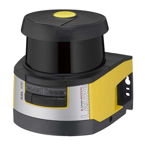
Page 13: Device Description
Performance Level (PL) in accordance with EN ISO 13849-1:2015 Scanner unit Connection unit Optics cover Alphanumerical display (displayed) LED indicators Mini-B USB connection (behind protective cap) Fig. 3.1: Device overview of RSL 400 safety laser scanners Leuze electronic GmbH + Co. KG RSL 420... -
Page 14: Device Overview
Up to 3 Up to 4 Up to 9 Up to 9 Configurable signal outputs Number of changeover-capable pro- 10 + 10 tective/warning field pairs E-stop linkage Four field mode (quads) Internal safe time delay Leuze electronic GmbH + Co. KG RSL 420... -
Page 15: Protective Function Of Rsl 400 Safety Sensors
Ä After use, seal the USB connection using a protection cap. Make sure that the protection cap is felt to engage when sealing. The IP degree of protection specified in the technical data is only achieved when the protection cap is closed. Leuze electronic GmbH + Co. KG RSL 420... -
Page 16: Connection Unit
• Quick-release connection to the scanner unit (see Quick Start Guide) for easy device swap-out NOTICE To ensure the IP protection and leak tightness of the devices, the supplied protection caps must always be placed on unused connections. Leuze electronic GmbH + Co. KG RSL 420... -
Page 17: Display Elements
Protective field free and linked sensor enabled (if applicable) Blue Free warning field Warning field interrupted Blue Four field mode: warning field 3 free Four field mode: warning field 3 interrupted Yellow Flashing Four field mode: warning field 2 interrupted Flashing Error Leuze electronic GmbH + Co. KG RSL 420... -
Page 18: Alphanumerical Display
Until downloading of configuration data is confirmed DOWNLOAD CONFIG During transfer of configuration data Level H +/- ..° V +/- .. ° Horizontal alignment in degrees: H H -3° V +9° Vertical alignment in degrees: V Leuze electronic GmbH + Co. KG RSL 420... -
Page 19: Field-Of-View Display
The loop guard for the optics cover prevents damage to the safety sensor caused by light contact with for- eign objects. The loop guard is available as an accessory (see chapter 17 "Order guide and accessories"). Leuze electronic GmbH + Co. KG RSL 420... -
Page 20: Configuration And Diagnostic Software Sensor Studio
• Each device DTM has a communication DTM that sets up and monitors the communication connec- tions to the sensor. NOTICE Only use the software for safety sensors manufactured by Leuze. System requirements To use the software, you need a PC or laptop with the following specifications: Hard disk space At least 250 MB free memory... - Page 21 RSL 400 device DTM. The password for the safety sensor only needs to be entered (i.e. the access level only needs to be changed) when the changes are downloaded to the safety sensor (see chapter 4.5.1 "Selecting access level"). Leuze electronic GmbH + Co. KG RSL 420...
-
Page 22: User Interface
The device managers (DTM) of the safety sensors are created and managed in the FDT frame menu. Device manager DTM Configuration projects for setting up the selected safety sensor are created and managed in the device managers (DTM) of the safety sensors. Leuze electronic GmbH + Co. KG RSL 420... -
Page 23: Fdt Frame Menu
Ä Start the Project Wizard in the FDT frame menu by clicking the button. NOTICE Information on the Project Wizard can be found in the online help for the FDT frame menu under Sensor Studio Options. Leuze electronic GmbH + Co. KG RSL 420... -
Page 24: Dtm Change
Ä Save the configuration settings as a configuration project on the PC. You can open the configuration project again at later time via File > Open or with the Sensor Studio Project Wizard ( Leuze electronic GmbH + Co. KG RSL 420... -
Page 25: Using Configuration Projects
ð Automatic connection to a connected safety sensor (Online) ð Device selection without communication connection (offline) ð Load a saved project again ð The project wizard displays the SEARCH DEVICES dialog box. Leuze electronic GmbH + Co. KG RSL 420... - Page 26 Search function Fig. 4.4: Communication DTM with search function ð The project wizard displays the device list of configurable safety sensors in the SEARCH DEVICES di- alog box. Fig. 4.5: Device selection in project wizard Leuze electronic GmbH + Co. KG RSL 420...
-
Page 27: Selecting Access Level
• Expert can change communication and diagnostics settings (default password = comdiag) • Engineer can additionally change the safety configuration (default password = safety) The password is case-sensitive (i.e. a distinction is made between upper-case and lower-case letters). Ä Confirm with [OK]. Leuze electronic GmbH + Co. KG RSL 420... -
Page 28: Identification
ð In the display of the safety sensor connected to the device manager (DTM), the message "PING re- ceived" flashes for ten seconds. Reset sensor Acknowledge messages and faults Set safety sensor to safety mode Leuze electronic GmbH + Co. KG RSL 420... -
Page 29: Settings
Create and save service file The service file contains all available information on the safety sensor as well as configuration and settings. When requesting support, send the service file to the Leuze customer service (see chapter 14 "Service and support"). - Page 30 Ä Generate a valid password. Note down the generated reset password. Ä Send the reset password to the Leuze customer service for confirmation (see chapter 14 "Service and support"). The device can now be switched off and the connection can be terminated.
-
Page 31: Functions
• Load the signed safety configuration from a file and transfer/download to the safety sensor • Transfer changed communication and diagnostics settings from the PC to the safety sensor • Print configuration data incl. protective/warning fields • Calibrate optics cover Leuze electronic GmbH + Co. KG RSL 420... -
Page 32: Function Modes Of Safety Sensor
1 FP / 1 PF + 1 WF Fixed selection of one field pair 5 FP / 5 PF + 5 WF Selection by signal input: • Overlapped monitoring 10 FP / 10 PF + 10 WF Selection by signal input: • Fixed changeover moment Leuze electronic GmbH + Co. KG RSL 420... -
Page 33: One Protective Function
B-CLEAR Switching output MELD – not safe Protective function B: protective field violation A-WF-VIO Switching output A1 Protective function A: Violation of warning field B-WF-VIO Switching output EA1 Protective function B: Violation of warning field Leuze electronic GmbH + Co. KG RSL 420... -
Page 34: Selectable Resolution For Hand, Leg And Body Detection
• The start/restart interlock function is taken over by a downstream safety-related component of the ma- chine control system. • It is not possible to walk behind or go around the effective protective field. Ä Allow for an optical and/or acoustic start warning. Leuze electronic GmbH + Co. KG RSL 420... -
Page 35: Start Interlock/Automatic Restart
• Restart interlock NOTICE For access guarding, the start/restart interlock function is mandatory. The protective device may only be operated without start/restart interlock in certain exceptional cases and under certain conditions acc. to EN ISO 12100. Leuze electronic GmbH + Co. KG RSL 420... -
Page 36: Field Pair Changeover
If the requirements on the time behavior of the field pair changeover are not maintained, the safety-related switching outputs switch off and a message is displayed (see chapter 12 "Diagnosis and troubleshooting"). Leuze electronic GmbH + Co. KG RSL 420... - Page 37 The field pair changeover from SFc to SFb may take place at time T01 = Tz minus the set changeover time at the earliest (danger G1 persists until Tz). Leuze electronic GmbH + Co. KG RSL 420...
-
Page 38: Changeover Of Five Field Pairs In Changeover Mode Overlapped Monitoring
Field pair A1.5 is active In the case of two protective functions, connection of control inputs F6 to F10 applies analogously for acti- vation of field pairs B1.1 to B1.5 for protective function B. Leuze electronic GmbH + Co. KG RSL 420... -
Page 39: Changeover Of Ten Field Pairs In Changeover Mode Fixed Changeover Moment
Field pair A1.10 is active In the case of two protective functions, connection of control inputs F6 to F10 applies analogously for acti- vation of field pairs B1.1 to B1.10 for protective function B. Leuze electronic GmbH + Co. KG RSL 420... -
Page 40: Monitoring Of Field Pair Changeover
Ä Activate the Reference contour monitoring function together with the definition of the protective field boundaries using the configuration and diagnostics software (see chapter 9.4.4 "Creating and configur- ing protective/warning field pairs"). Leuze electronic GmbH + Co. KG RSL 420... -
Page 41: Field Pair Monitoring
• The safety circuit is closed or both contacts have been closed simultaneously within 0.5 s. Activation of the function Ä Activate the linkage using the configuration and diagnostics software (see chapter 9.4.3 "Activating pro- tective function and contactor monitoring"). Leuze electronic GmbH + Co. KG RSL 420... -
Page 42: 5.12.2 Linkage Of Electronic Safety-Related Switching Outputs
(see chapter 9.6 "Configuring signal outputs"). For an overview of all logic and electrical signals of the safety sensor, see chapter 15.4 "Representation of safety sensor status". Leuze electronic GmbH + Co. KG RSL 420... -
Page 43: Applications
In accordance with EN ISO 13855, resolutions from 14 to 40 mm make sense here. This yields the necessary safety distance for finger protection, among others (see chapter 7.3 "Stationary point of operation guarding"). Leuze electronic GmbH + Co. KG RSL 420... -
Page 44: Stationary Access Guarding
This is why the start/restart interlock function is vital for access guarding. Safety sensor Reference contour Danger zone 1, protective function activated Danger zone 2, protective function deactivated Fig. 6.2: Stationary access guarding Leuze electronic GmbH + Co. KG RSL 420... -
Page 45: Mobile Danger Zone Guarding
Protective field 1 for forward travel, deactivated Protective field 2 for forward travel, activated Protective field 1 for reverse travel, activated Protective field 2 for reverse travel, deactivated Warning field for reverse travel Fig. 6.3: Mobile danger zone guarding Leuze electronic GmbH + Co. KG RSL 420... - Page 46 Protective field 1 for forward travel, deactivated Protective field 2 for forward travel, activated Protective field 1 for reverse travel, activated Protective field 2 for reverse travel, deactivated Warning field for reverse travel Fig. 6.4: Mobile danger zone guarding Leuze electronic GmbH + Co. KG RSL 420...
-
Page 47: Danger Zone Safeguarding On Side-Tracking Skates
Protective and warning field pair for side guarding, left, activated Protective and warning field pair for side guarding, right, activated Protective and warning field pair for reverse travel, deactivated Fig. 6.5: Mobile side guarding on side-tracking skates Leuze electronic GmbH + Co. KG RSL 420... -
Page 48: Vehicle Navigation
• Angle of incidence of the laser beam on the object surface 0°: vertically incident light • Share of area of the light spot on the object 100%: the light spot lies completely on the measured object Leuze electronic GmbH + Co. KG RSL 420... - Page 49 3M™ Diamond Grade 983-10™. The lower curve (4) shows the typical, distance-dependent change of the signal strength for a white, natu- rally scattering surface with 90% diffuse reflection, e.g., a white wall. Leuze electronic GmbH + Co. KG RSL 420...
-
Page 50: Mounting
= Stopping time of the machine [mm] = Additional distance to the safety distance NOTICE If longer stopping times are determined during regular inspections, an appropriate additional time must be added to t Leuze electronic GmbH + Co. KG RSL 420... -
Page 51: Suitable Mounting Locations
• Make sure that the scanning range of the safety sensor is not limited. To mount the safety sensor tak- ing the scanning range into consideration, a template must be attached to the top cover of the safety sensor. Leuze electronic GmbH + Co. KG RSL 420... - Page 52 Ä Align the mounted safety sensor horizontally and vertically using the integrated electronic spirit level. • For the electronic spirit level to work, the supply voltage of 24 V must be present at the safety sensor. Leuze electronic GmbH + Co. KG RSL 420...
- Page 53 You can easily test the safety sensor along this marking. After mounting, you can electrically connect (see chapter 8 "Electrical connection"), start up, align (see chapter 10 "Starting up the device"), and test (see chapter 11 "Testing") the safety sensor. Leuze electronic GmbH + Co. KG RSL 420...
-
Page 54: Mounting Examples
Safety sensor Column BT856M mounting bracket Fig. 7.3: Example: mounting on a post all dimensions in mm Safety sensor BT840M mounting bracket Fig. 7.4: Example: mounting on a chamfered corner Leuze electronic GmbH + Co. KG RSL 420... -
Page 55: Information On Protective Field Dimensioning
There is an area behind the safety sensor that the safety sensor does not monitor. Unmonitored areas can also materialize, e.g. if you install a safety sensor on a rounded off vehicle front. It must not be possible to walk behind unmonitored areas. Leuze electronic GmbH + Co. KG RSL 420... - Page 56 Stepping behind protection by countersinking into the machine contour Ä Use a physical cover set at an angle over the safety sensor if you expect that the safety sensor will be used as a climbing aid or standing surface. Leuze electronic GmbH + Co. KG RSL 420...
- Page 57 Shielding prevents reciprocal influencing of safety sensors set up beside one another Ä Install the safety sensors off-set on the height. Minimum distance, min. 100 mm Scan level Fig. 7.9: Height offset mounting, parallel alignment Leuze electronic GmbH + Co. KG RSL 420...
-
Page 58: Stationary Danger Zone Guarding
120 ms or higher. Ä Determine the machine/system's stopping time t If data is not available, you can commission Leuze to perform measurements; see chapter 14 "Service and support". Ä If an increase in the stopping time within the regular test periods is to be expected, take an additional time into account for the machine's stopping time t... - Page 59 , where required) REFL Largest protective field radius without additional distances, measured from the rotation axis of the rotary mirror Fig. 7.12: Defining the protective field contour for a stationary, horizontal protective field Leuze electronic GmbH + Co. KG RSL 420...
- Page 60 Ä Prevent obstructions within the calculated protective field boundaries. If this is not possible, implement protective measures so that the point of operation cannot be reached from out of the shadow of the ob- struction. Leuze electronic GmbH + Co. KG RSL 420...
-
Page 61: Stationary Point Of Operation Guarding
80 ms or higher. Ä Determine the machine/system's stopping time t If data is not available, you can commission Leuze to perform measurements (see chapter 14 "Service and support"). Ä If an increase in the stopping time within the regular test periods is to be expected, take an additional time into account for the machine's stopping time t... -
Page 62: Stationary Access Guarding
With higher val- ues it can happen that a person might not be detected when passing through the protective field with an approach speed of 1600 mm/s. Leuze electronic GmbH + Co. KG RSL 420... -
Page 63: Mobile Danger Zone Guarding On Agvs
Mounting Ä Determine the machine/system's stopping time t If data is not available, you can commission Leuze to perform measurements (see chapter 14 "Service and support"). Ä If an increase in the stopping time within the regular test periods is to be expected, take an additional time into account for the machine's stopping time t... -
Page 64: Minimum Distance D
Its size depends on the biggest radius R from the safety sensor mirror's rotary axis to the protective field boundary without Z . The position of the rotary mirror axis depends on the installation situation. Leuze electronic GmbH + Co. KG RSL 420... -
Page 65: Protective Field Dimensions
A full brake with a subsequent interruption of the protective field is then executed moderately and is less demanding on the vehicle's drives. Dimension the minimum distance D for the maximum speed as if the speed reduction initiated by the warning field had not happened. Leuze electronic GmbH + Co. KG RSL 420... -
Page 66: Mobile Side Guarding On Agvs
Ä Mount the mounting system on the wall mount or on the mounting bracket for floor mounting. Ä Attach the safety sensor to the mounting system. Tightening the screws fixes the safety sensor in position. Ä Align the safety sensor using the integrated electronic spirit level. Leuze electronic GmbH + Co. KG RSL 420... -
Page 67: Loop Guard
BTU800M mounting system Loop guard Safety sensor Fig. 7.18: Loop guard Ä Attach the safety sensor to the mounting system. Ä Engage the loop guard for the optics cover from above into the mounting system. Leuze electronic GmbH + Co. KG RSL 420... -
Page 68: Electrical Connection
In the case of wiring that continues beyond the device or during repairs to connectors, the user must ensure that cables or conductors that have defectively disconnected cannot result in con- tact with other signals. Ä Use suitable terminals. Ä Use heat-shrink tubing, wire-end sleeves or similar. Leuze electronic GmbH + Co. KG RSL 420... -
Page 69: Electrical Supply
Ä For permanent connection, connect the safety sensor to the Ethernet connection of the con- nection unit. The control cable is permanently attached to the connection unit. A protection cap on the connection unit protects the communication interface when no PC is connected. Leuze electronic GmbH + Co. KG RSL 420... -
Page 70: Connection Cable, Control
5 function inputs for field pair changeover, protective function A Violet Gray/pink Red/blue White/Green Brown/Green Linkage input (E-Stop, OSSD – external device) White/Yellow Linkage input (E-Stop, OSSD – external device) Yellow/Brown Output signal State signaling, configurable Leuze electronic GmbH + Co. KG RSL 420... -
Page 71: Connection Cable With M30 Connector
White/Green Brown/Green Linkage input (E-Stop, OSSD – external device) White/Yellow Linkage input (E-Stop, OSSD – external device) Yellow/Brown Output signal state signaling, configurable Connector Shield Functional earth, connection cable shield housing Leuze electronic GmbH + Co. KG RSL 420... -
Page 72: Pin Assignment Of M12 Ethernet Interface (Communication) ( D-Coded)
Connection unit CU416 M5 2x Connection cable, connection to the machine M12 socket, D-coded, Ethernet communication connection Connection for functional earth with M5 x 10 self-cutting/self-tapping (gas tightness) and ground strap Fig. 8.3: Connection unit CU416 Leuze electronic GmbH + Co. KG RSL 420... - Page 73 16.8 V. NOTICE The recommended operating voltage is at least 19 V! Leuze recommends an operating voltage U of at least 19 V at the input terminals of the con- nection unit. Ä The operating voltage should not be allowed to drop below the recommended value if possi- ble.
-
Page 74: Cable Lengths According To The Operating Voltage
16.8 V. NOTICE The recommended operating voltage is at least 19 V! Leuze recommends an operating voltage U of at least 19 V at the input terminals of the con- nection unit. Ä The operating voltage should not be allowed to drop below the recommended value if possi- ble. -
Page 75: Circuit Diagram Example
Electrical connection Circuit diagram example Spark extinction circuit, suitable spark extinction provided Fig. 8.6: RSL 420 with MSI-SR4B safety relay Leuze electronic GmbH + Co. KG RSL 420... -
Page 76: Configuring The Safety Sensor
Ä For example, make sure that the distance range in which manipulation is possible cannot be accessed by personnel under normal operating conditions. Leuze electronic GmbH + Co. KG RSL 420... - Page 77 To document the configuration, you can create a PDF file of the safety configuration or save the config- uration and settings in an *.xml file. Leuze electronic GmbH + Co. KG RSL 420...
-
Page 78: Connecting Safety Sensor To Pc
Use active USB cables if longer cable lengths are required. NOTICE Ä If possible, use the ready-made cables from Leuze (see chapter 17 "Order guide and acces- sories"). • Connect the USB cable to the safety sensor and the PC. -
Page 79: Communication Between Safety Sensor And Pc
RSL 400 device DTM. The password for the safety sensor only needs to be entered (i.e. the access level only needs to be changed) when the changes are downloaded to the safety sensor (see chapter 4.5.1 "Selecting access level"). Leuze electronic GmbH + Co. KG RSL 420... - Page 80 The device manager (DTM) starts without querying the access level of the user. During commu- nication with the safety sensor, the safety sensor does however query the access level of the user. To change the access levels, see chapter 9.9 "Selecting access level". Leuze electronic GmbH + Co. KG RSL 420...
-
Page 81: Configuring Protective Function
The changeover-capable protective/warning field pairs for the selected protective function are defined in configuration banks. Ä In the CONTACTOR MONITORING list, activate the contactor monitoring of the safety sensor: • EDM OSSD A • E-Stop • OSSD linkage Leuze electronic GmbH + Co. KG RSL 420... -
Page 82: Creating And Configuring Protective/Warning Field Pairs
Ä In the START-UP BEHAVIOR dialog box, select the start-up behavior and the restart time of the safety sensor. NOTICE Configuration of the start-up behavior is only implemented if the corresponding electrical signal connections exist; see chapter 8 "Electrical connection". Leuze electronic GmbH + Co. KG RSL 420... - Page 83 Ä In the CONFIGURATION menu, click the field pair the protective and warning fields of which you want to define. Ä Click the button and define the contours and boundaries of the protective field. Leuze electronic GmbH + Co. KG RSL 420...
-
Page 84: Configuring Field Pair Monitoring
Ä In the CONFIGURATION menu, click the Parameters option of the field pair the protective and warning fields of which you have defined. Ä Select the monitoring mode for the field pair in the Field pair monitoring list. Leuze electronic GmbH + Co. KG RSL 420... -
Page 85: Defining Permissible Field Pair Changeovers
Ä In the MONITORING OF FIELD PAIR CHANGEOVER dialog box, activate the Monitoring option. Ä In the MONITORING OF FIELD PAIR CHANGEOVER dialog box, define the sequence of field pair changeovers according to your conditions. Ä Click the [Confirm] button. Leuze electronic GmbH + Co. KG RSL 420... -
Page 86: Configuring Signal Outputs
• If no individual password has been defined for the access level Engineer, use the preset default password (safety). NOTICE Alternatively, you can transfer a configuration project saved as a file on the PC directly to the safety sensor. Leuze electronic GmbH + Co. KG RSL 420... - Page 87 Ä Observe the relevant safety notices regarding changes to the configuration (see chapter 9.1 "Defining safety configuration"). Ä Check the displayed signature. Leuze electronic GmbH + Co. KG RSL 420...
-
Page 88: Selecting Access Level
Ä In the DTM menu bar, click the [Reset safety configuration] button. ð Users with the access level Engineer can additionally transfer the changed safety configuration to the safety sensor (see chapter 9.8 "Transferring configuration project to safety sensor"). Leuze electronic GmbH + Co. KG RSL 420... -
Page 89: Starting Up The Device
Ä Unlock the start/restart interlock using the reset button. The safety-related switching outputs are only enabled if you hold down the reset button for between 0.12 s and 4 s. Leuze electronic GmbH + Co. KG RSL 420... -
Page 90: Shutting Down
Ä Change the configuration parameters of the safety sensor using the configuration and diag- nostic software according to the operating range of the replacement scanner unit. Leuze electronic GmbH + Co. KG RSL 420... - Page 91 Ä If you transferred a new configuration to the safety sensor, check the safety sensor according to the routine for initial start-up (see chapter 11.1.1 "Checklist for integrator – to be performed prior to the ini- tial start-up and following modifications"). Leuze electronic GmbH + Co. KG RSL 420...
-
Page 92: Testing
Ä If you answer one of the items on the check list with no, the machine must no longer be op- erated (see table below). Ä EN IEC 62046 contains additional recommendations on testing protective devices. Leuze electronic GmbH + Co. KG RSL 420... - Page 93 Are settings that could result in an unsafe state possible only by means of key, password or tool? Are there incentives that pose stimulus for tampering? Were the operators instructed prior to starting work? Leuze electronic GmbH + Co. KG RSL 420...
-
Page 94: To Be Performed Periodically By Competent Persons
Ä If you answer one of the items on the check list with no, the machine must no longer be op- erated (see chapter 11.1.1 "Checklist for integrator – to be performed prior to the initial start- up and following modifications"). Leuze electronic GmbH + Co. KG RSL 420... - Page 95 – are the obviously dangerous machine parts stopped with- out noticeable delay? Protective device with presence detection: the protective field is interrupted with the test object – does this prevent operation of the obviously dangerous machine parts? Leuze electronic GmbH + Co. KG RSL 420...
-
Page 96: Diagnosis And Troubleshooting
Ä Analyze the cause of the fault using the diagnostics displays and rectify the fault. Ä If you are unable to rectify the fault, contact the Leuze branch responsible for you or call the Leuze customer service (see chapter 14 "Service and support"). - Page 97 Swap out the safety sensor or change the known parameter. configuration. The type of safety sensor must be the same as the type stored in the connec- tion unit or in the Sensor Studio software. Leuze electronic GmbH + Co. KG RSL 420...
- Page 98 Field pair changeover without request. Check the request signal for field pair changeover or change the safety configura- tion. U0849 Field pair changeover not permitted. Check the wiring of the field pair inputs. Leuze electronic GmbH + Co. KG RSL 420...
- Page 99 (Without switch-off of the OSSDs) F..The monitoring functions have detected an Create the service file (see chapter 4.5.5 "DI- internal error. AGNOSIS") and contact the Leuze customer service (see chapter 14 "Service and sup- port"). Leuze electronic GmbH + Co. KG RSL 420...
-
Page 100: Care, Maintenance And Disposal
Ä Check the safety sensor according to the routine for initial start-up (see chapter 11.1.1 "Checklist for in- tegrator – to be performed prior to the initial start-up and following modifications"). Leuze electronic GmbH + Co. KG RSL 420... -
Page 101: Cleaning The Optics Cover
After cleaning is complete, the safety sensor resets itself auto- matically. Ä Clean the optics cover over the entire 360° range. Ä Soak cloth with cleaning agent. Ä Wipe optics cover free in one swipe. Leuze electronic GmbH + Co. KG RSL 420... -
Page 102: Servicing
The device does not normally require any maintenance by the operator. Repairs to the device must only be performed by the manufacturer. Ä For repairs, contact your responsible Leuze subsidiary or Leuze customer service (see chapter 14 "Ser- vice and support"). -
Page 103: Service And Support
Service and support Service and support Service hotline You can find the contact information for the hotline in your country on our website www.leuze.com under Contact & Support. Repair service and returns Defective devices are repaired in our service centers competently and quickly. We offer you an extensive service packet to keep any system downtimes to a minimum. -
Page 104: Technical Data
Tab. 15.4: Protective field range Device range Resolution [mm] Protective field range [m] 3.00 4.50 6.25 8.25 3.00 4.50 6.25 8.25 3.00 4.50 6.25 8.25 3.00 4.50 6.25 6.25 3.00 4.50 4.50 4.50 Leuze electronic GmbH + Co. KG RSL 420... - Page 105 Measurement range: 0 m … 9 m • Diffuse reflection: 20% … retro-reflector Measurement range: 0 m … 25 m Laser spot height 10 m 60 mm 20 m 165 mm 30 m 265 mm 40 m 285 mm Laser spot width 10 m 13 mm 20 m 24 mm 30 m 40 mm 40 m 57 mm Leuze electronic GmbH + Co. KG RSL 420...
- Page 106 M12-4 connector, D-coded Tab. 15.9: Inputs Reset +24 V, dynamically monitored (0.12 s to 4 s) Field pair changeover Selection of 10 field pairs via 5 control cables +24 V, dynamically monitored Signal definition: High/logical 1 16 - 30 V Low/logical 0 < 3 V Leuze electronic GmbH + Co. KG RSL 420...
- Page 107 Auxiliary contact of (EA1) (-20 mA) (-10 mA) power contactor (EDM) AX=output 100 mA Lamp (PNP only) Current-limited, short-circuit proof (-20 mA) Control input (PNP/ (A1, MELD) NPN) Signal definition: High/logical 1 16 - 30 V Low/logical 0 < 3 V Leuze electronic GmbH + Co. KG RSL 420...
- Page 108 Weight of standard version incl. connection unit Approx. 3 kg Distance, beam level center to bottom housing edge 104 mm Tab. 15.16: Patents US patents US 7,656,917 B US 7,696,468 B US 8,520,221 B US 2016/0086469 A Leuze electronic GmbH + Co. KG RSL 420...
-
Page 109: Dimensions
Technical data 15.2 Dimensions M5 2x all dimensions in mm Scan level Fig. 15.2: Dimensions safety laser scanner with connection unit Leuze electronic GmbH + Co. KG RSL 420... - Page 110 Fig. 15.4: Minimum space requirements for installation and replacement of scanner unit all dimensions in mm Reference point for distance measurement and protective field radius Fig. 15.5: Dimensions of scanning range Leuze electronic GmbH + Co. KG RSL 420...
-
Page 111: Dimensioned Drawings: Accessories
Technical data 15.3 Dimensioned drawings: Accessories 157,5 166,3 all dimensions in mm Fig. 15.6: BTU800M mounting system Leuze electronic GmbH + Co. KG RSL 420... - Page 112 Technical data all dimensions in mm Fig. 15.7: BTF815M mounting bracket Leuze electronic GmbH + Co. KG RSL 420...
- Page 113 Technical data all dimensions in mm Fig. 15.8: BTF830M mounting bracket Leuze electronic GmbH + Co. KG RSL 420...
- Page 114 Technical data all dimensions in mm Fig. 15.9: Loop guard BTP800M Leuze electronic GmbH + Co. KG RSL 420...
- Page 115 Technical data 205,2 all dimensions in mm Fig. 15.10: BT840M mounting bracket all dimensions in mm Fig. 15.11: Mounting bracket BT840M, view A Leuze electronic GmbH + Co. KG RSL 420...
- Page 116 Technical data 233,5 all dimensions in mm Fig. 15.12: BT856M mounting bracket all dimensions in mm Fig. 15.13: Mounting bracket BT856M, view A Leuze electronic GmbH + Co. KG RSL 420...
- Page 117 Technical data 120,4 all dimensions in mm Fig. 15.14: Drilling template for adapter plate, RS4/ROD4 BT800MA Leuze electronic GmbH + Co. KG RSL 420...
- Page 118 Technical data 157,5 166,3 all dimensions in mm The mounting plate BTU804MA supplements the old mounting system of the RS4/ROD4 for the mounting system BTU800M. Fig. 15.15: BTU804MA mounting plate Leuze electronic GmbH + Co. KG RSL 420...
-
Page 119: Representation Of Safety Sensor Status
OSSD state Protective function A B-OSSD OSSD state Protective function B Emergency stop and parking Status-Input-SE Status of the inputs SE1 and SE2 E-STOP Mode-PARK Park request fulfilled parked Reserved Reserved Reserved Reserved Reserved Reserved Leuze electronic GmbH + Co. KG RSL 420... - Page 120 EDM input Protective function B Linkage input Linkage input PNP-NPN PNP/NPN changeover Output Output Output Output MELD Output Reserved 8-11 31-0 SCAN Consecutive numbering of scans value uint32 Resetting to 0 by switching off Leuze electronic GmbH + Co. KG RSL 420...
- Page 121 A-PF-VIO-SEG-2 Status of active protective field violation free segment Protective function A A-FP-SEL-1 Defined field pair selected selected Protective function A A-FP-SEL-2 Defined field pair selected selected Protective function A Reserved Reserved Leuze electronic GmbH + Co. KG RSL 420...
-
Page 122: Standards And Legal Regulations
• Product Safety Law (ProdSG) • Standards for risk assessment, e.g. • EN ISO 12100 • EN ISO 13849-1, -2 • IEC/EN 61508-1 to -7 • EN IEC 62061 • IEC/EN 60204-1 • EN ISO 13849-1 • EN ISO 13855 • EN IEC 61496-3 • EN ISO 3691-4 • EN IEC 62046 Leuze electronic GmbH + Co. KG RSL 420... -
Page 123: Order Guide And Accessories
1 OSSD pair; 10 field pairs; 4 IOs; protective field range max. 6.5 m Connection: cable, 16-wire, length 25 m Ethernet: M12, 4-pin 53800220 RSL420-XL/CU416-25 1 OSSD pair; 10 field pairs; 4 IOs; protective field range max. 8.25 m Connection: cable, 16-wire, length 25 m Ethernet: M12, 4-pin Leuze electronic GmbH + Co. KG RSL 420... - Page 124 Connection: cable, 16-wire, length 5 m Ethernet: M12, 4-pin 53800270 RSL425-XL/CU416-5 1 OSSD pair; 10 field pairs; 4 IOs; data output for navigation, pro- tective field range max. 8.25 m Connection: cable, 16-wire, length 5 m Ethernet: M12, 4-pin Leuze electronic GmbH + Co. KG RSL 420...
- Page 125 Connection: 0.3 m cable with 16-pin connector Ethernet: M12, 4-pin 53800281 RSL425-L/CU416-300- 1 OSSD pair; 10 field pairs; 4 IOs; data output for navigation, pro- tective field range max. 6.5 m Connection: 0.3 m cable with 16-pin connector Ethernet: M12, 4-pin Leuze electronic GmbH + Co. KG RSL 420...
- Page 126 Connection: cable, 16-wire, length: 25 m Ethernet: M12, 4-pin 53800125 CU411-RS4 RS4 adapter Connection: cable, 11-wire, SUB-D 15, length: 0.6 m Ethernet: M12, 4-pin 53800180 CU416-300-WPU Connection: cable, 16-wire, with M30 connector, length: 0.3 m Ethernet: M12, 4-pin Leuze electronic GmbH + Co. KG RSL 420...
- Page 127 Cleaning fluids 430400 Cleaning set 1 Cleaning fluid for plastic, 150 ml, cleaning cloths, 25x, soft, fuzz- free 430410 Cleaning set 2 Cleaning fluid for plastic, 1,000 ml, cleaning cloths, 100x, soft, fuzz- free Leuze electronic GmbH + Co. KG RSL 420...
-
Page 128: Ec Declaration Of Conformity
EC Declaration of Conformity EC Declaration of Conformity The safety laser scanners of the RSL 400 series have been developed and manufactured in accordance with the applicable European standards and directives. Leuze electronic GmbH + Co. KG RSL 420...
Need help?
Do you have a question about the RSL 420 and is the answer not in the manual?
Questions and answers